03/27/08 Page 6 of 7
LINE 6 CONFIDENTIAL
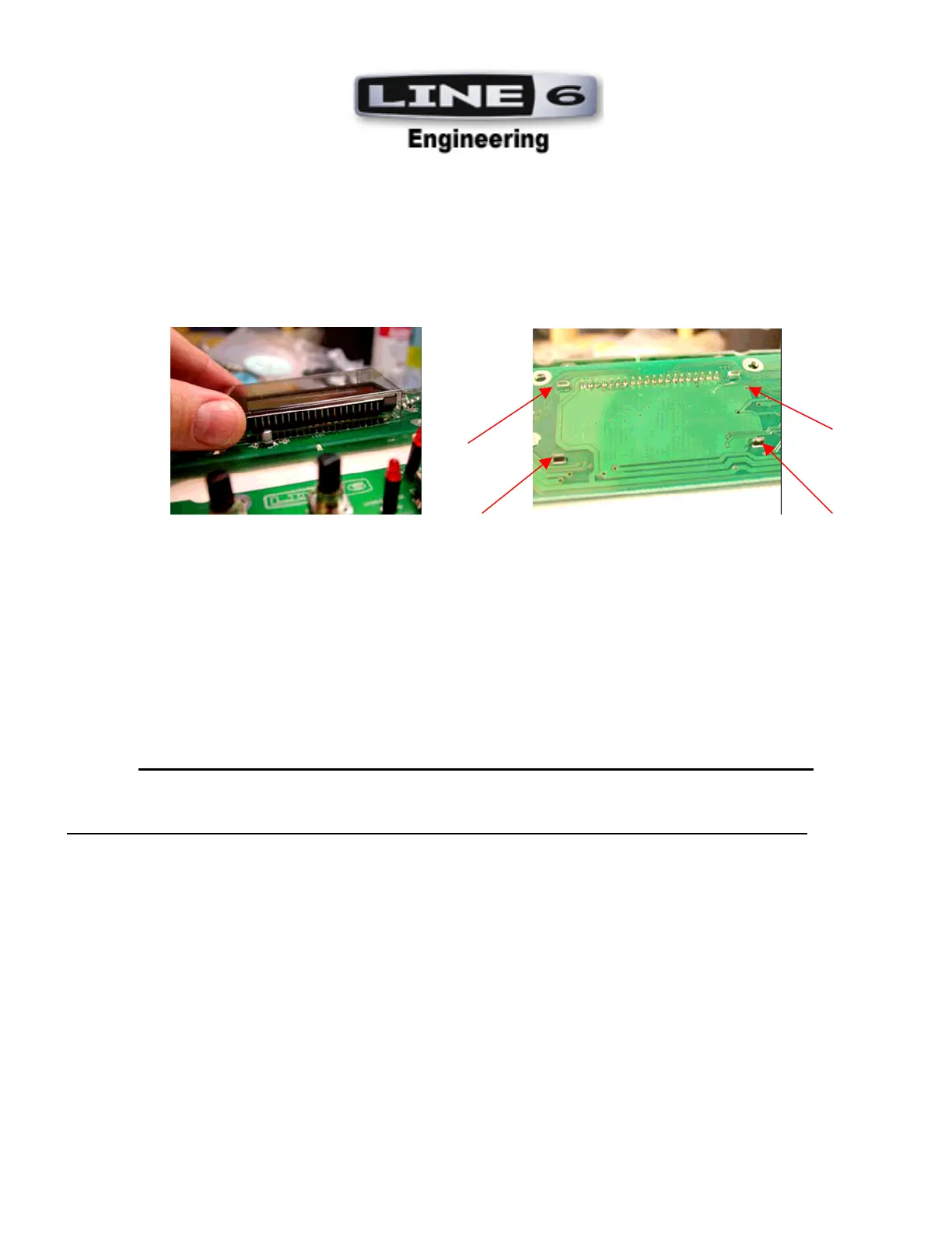
10.
Installation of LCD Bezel: LCD Bezel (30-27-0298) should be snapped into place on User Interface Upper
PCB (35-00-0272). Turn PCB upside down and visually confirm that the bezel’s ends have all snapped
through. See Photos.
END OF USER INTERFACE BREAKAWAY PCBA ASSEMBLY INSTRUCTIONS
PCBA ASSEMBLY INSTRUCTIONS REVISION CHANGE HISTORY
REVISION NOTES DATE RELEASED BY
A - Release for both Beta and Production, unless revised 03/13/2008 ANTHONY PASCUZZO
B
- Instruction updated to include Ribbon Cable Assemblies. 03/27/2008 ANTHONY PASCUZZO
C - Instruction updated to correct the tact switch assembly instruction 4/4/08 A.P.
 Loading...