Line 6 Mechanical Engineering
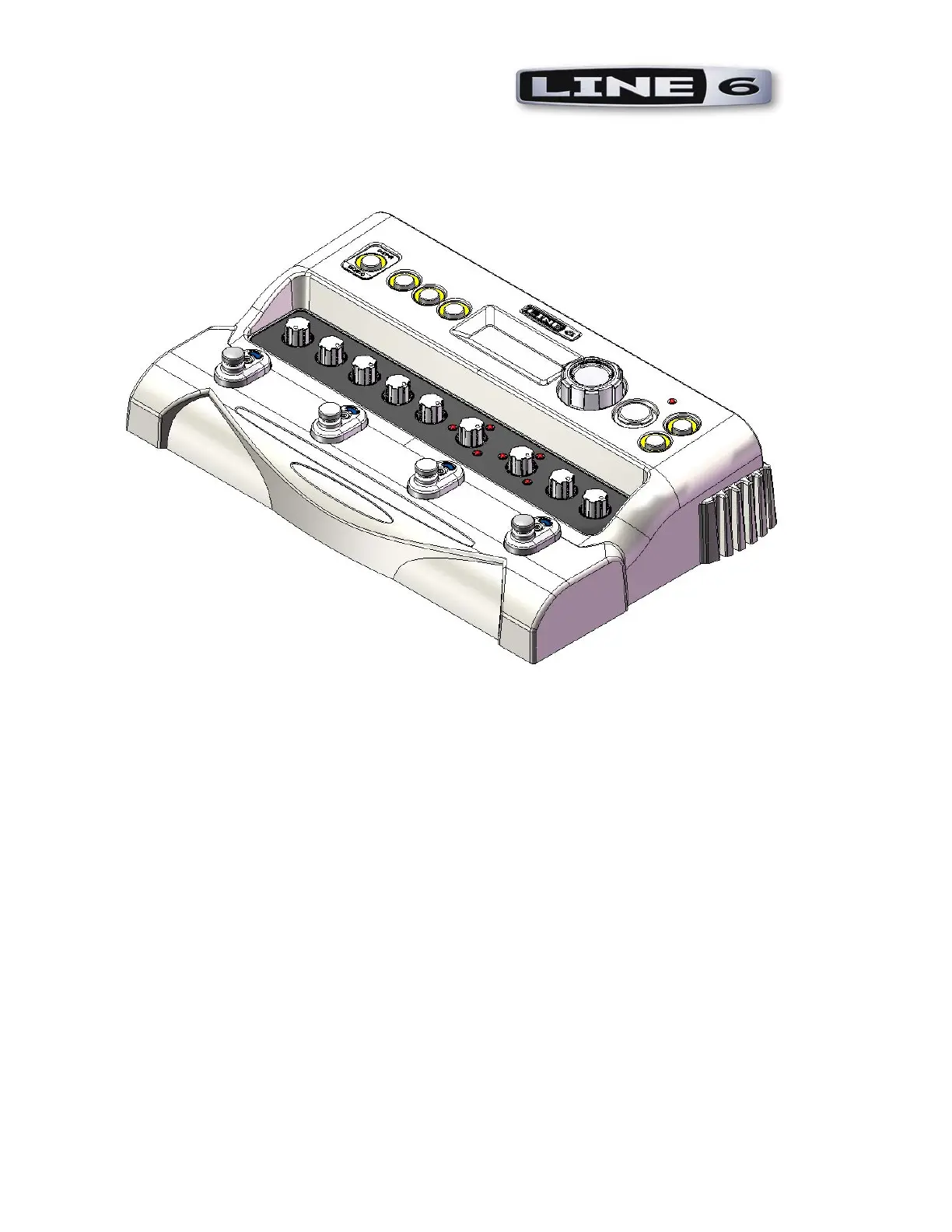
FloorJam F8-1 Complete Unit
Assembly Instructions Rev B
Document # L6D000184
Confidential Page 1 of 22 5/23/2008
Forward and Notes
The information in this booklet applies to the F8-1 Complete Unit. It is suggested that the steps for
assembly follow the order presented in these instructions.
These instructions deal with the assembling of the major subassemblies, the final product, and
quality/inspection considerations. See also the Related Electrical assembly documentation for major
considerations in assembling the electrical components of the PCBs (through the soldering process and
preparation of the board for addition of custom components).
A note on the text: the illustrations in this book are for reference only. In some cases, color and geometry
of illustrations may not accurately reflect the color or exact geometry of actual parts.
• Unless otherwise noted, all dimensions are in inches.
• Drawings are not to scale.
• Torque value tolerance +/- .5 in.-lbs. Do not over tighten any components.
• For clarity, not all component details are shown. This is especially true with respect to cable assemblies.
They are often omitted from views to provide a clearer picture of the material discussed. Do not be
confused by the absence (or unexpected presence) of any component in the illustrations in this book.
 Loading...