Line 6 Mechanical Engineering
FloorJam F8-1 Complete Unit
Assembly Instructions Rev B
Document # L6D000184
Confidential Page 20 of 22 5/23/2008
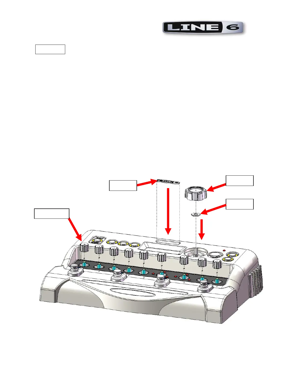
STEP 14
P/N required:
1 each 30-60-0006 LOGO
9 each 30-45-0019 KNOB POT .55 DIA x .50 HT PLASTIC CHROME PLATED
1 each 30-45-0017 KNOB 1.4" OD x .21" ID x .51" HT CHROME PLATED
Remove the protective backing from the LOGO.
Firmly press into the recess in the CHASSIS as shown.
LOGO shall be oriented such that it is readable in the direction shown.
Press one KNOB fully onto the shaft of each of the nine potentiometers.
Install NUT onto ENCODER.
Tighten nut to 8 -10 in-lbs.
Press one KNOB onto the shaft of the encoder on the right side of the DISPLAY BEZEL.
KNOB
LOGO
9x KNOB
NUT
 Loading...