Do you have a question about the Linear 2GIG-PANIC1-345 and is the answer not in the manual?
Details on the wireless panic button's functionality, range, and mounting options.
Lists the items included in the panic button remote package.
Emphasizes regular battery checks and replacement for critical use.
Procedure for removing the panic button's top cover using a screwdriver.
Steps for gently removing the old battery from the compartment.
Details compliance with FCC rules regarding interference and radiation.
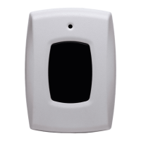
The 2GIG-PANIC1-345 Panic Button Remote is a compact, battery-powered, wireless device designed to transmit an emergency signal to a control panel. This panic button can be activated from any location within the radio frequency (RF) range of the control panel, regardless of whether the security system is armed or disarmed. Its primary function is to provide a quick and reliable way to signal an emergency, enhancing personal safety and security.
One of the key usage features of this panic button is its versatility in mounting and wearability. Users have the option to mount the device in a convenient wall location, making it easily accessible in a fixed spot. Alternatively, for mobile use, the panic button can be worn using one of several included accessories: a lanyard, a wristband, a belt clip, or a car-visor clip. This flexibility ensures that the panic button can be kept close at hand in various situations, whether at home, in a vehicle, or on the go. The device is also completely water-resistant, adding to its durability and reliability in different environments. To prevent accidental activations, the panic button incorporates a five-second button lockout feature, requiring a sustained press to trigger an alarm.
Activating the panic button is a straightforward process. To transmit an emergency signal, the user needs to press and hold the panic button for approximately two seconds. Upon activation, a red LED indicator will illuminate, confirming that a signal is being sent to the control panel. Once the control panel receives the signal, it will sound an alarm and display a "System in Alarm" message. To silence the alarm, any valid user code can be entered. An alarm report is also transmitted to the monitoring service. After acknowledging that the alarm report was sent by tapping "OK," users can clear the alarm history on the control panel by tapping "Clear Alarm History" and then "OK."
Maintenance of the panic button primarily involves battery management to ensure its continuous functionality. The device operates on a single Panasonic CR 2032 or equivalent Lithium battery. It is crucial to maintain the battery in good condition, as its proper functioning is imperative in duress situations. Users and qualified installation personnel are advised to check the battery regularly, at least once or more times per year. Under typical conditions, the battery life is approximately two years. When the battery is low, the control panel's Home screen will display a trouble notification. To ensure the panic button is always available during an emergency, it is recommended to replace the battery as soon as the low battery notification appears.
Replacing the battery involves a few simple steps. First, a small, flathead screwdriver should be inserted into the opening on the panic button to remove the top cover. Next, the flathead screwdriver is gently inserted between the battery and one of the metal clips in the battery compartment to remove the old battery. The replacement battery should then be inserted with the positive (+) sign facing up. If the circuit board is removed during this process, it is important to ensure that the LED aligns with the appropriate hole on the top cover before replacing the top cover. After replacing the battery, it is essential to test the panic button to verify its functionality and ensure it has quality radio frequency (RF) communications with the control panel.
Several warnings are provided regarding battery handling. It is critical to always use the recommended replacement batteries, ensuring they are new, in good condition, and fully charged. Batteries should never be inserted in the wrong direction, recharged, or disassembled. They should also not be placed in fire or water. Furthermore, batteries must always be kept away from small children, and if swallowed, medical attention should be sought promptly. Used batteries should be disposed of or recycled in accordance with local hazardous waste recovery and recycling regulations.
Programming the panic button into the control panel is also a key step in its setup. While the manual does not detail the programming steps, it refers users to the Control Panel's Installation & Programming Guide for instructions on how to program a wireless sensor. This ensures that the panic button is properly integrated into the security system and can effectively communicate with the control panel.
In summary, the 2GIG-PANIC1-345 Panic Button Remote is a versatile and reliable emergency signaling device designed for ease of use and personal safety. Its flexible wearability options, straightforward activation process, and clear maintenance guidelines contribute to its effectiveness as a critical component of a security system. Regular battery checks and proper replacement procedures are vital to ensure the device is always ready to function when needed most.
| Type | Panic Button |
|---|---|
| Frequency | 345 MHz |
| Battery Life | 3-5 Years |
| Supervisory Signals | Yes |
| Color | White |
| Compatibility | 2GIG Systems |
| Battery Type | CR2032 |
| Mounting | Keychain or Wall Mount |
| Range | 350 ft, open air |