Controller Series E1031/2031/4031 V3
NTI AG Installation: E1031/E2031/E4031 V3 series / 28.07.2010 Page 4/17
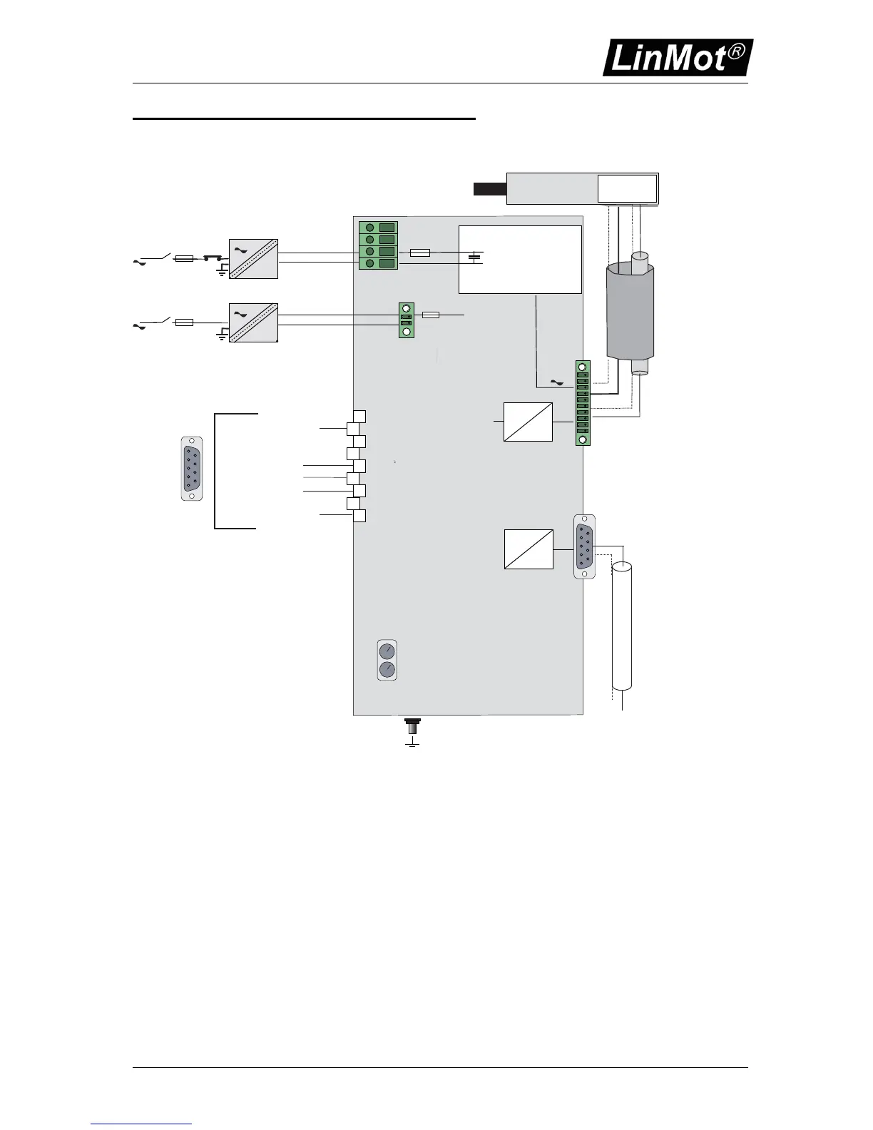
E1031 series Function and Wiring
2-Phase Powerstage (s)
72VDC (24..85VDC)
8A Phase Current
1
2
3
4
5
6
7
8
9
RS232
TTL
0-5V
A/D
Mot A ( addtional Motors B,C,D)
Com. RS232
Linear Motor
Motor Internal
Hall Sensors
Motor Phases*
Hall Sensors* /Temp Sensor
*use special double shielded Linear
Motor cable (see catalogue)
for RS232 PC connection use 1:1cable
Pin 2 - Pin 2, Pin 3 - Pin 3, Pin 5 - Pin 5
min. 0.5mm2 / AGW20 for 3A
AC-Mains
- Circuit Breaker
- Fuse
Emergency
Stop Breaker
=
+
48...72VDC
Power Supply motor
PWR motor
GND
8 AT (E1031)
16 AT (else)
signal components
5
4
3
2
1
9
8
7
6
DP
E1031
Controller
use only
shielded cables
10
1
ID High
ID Low
GND (isolated)
CNTR-P
RxD/TxD-P
6
1
2
7
4
8
3
9
5
RxD/TxD-N
+ 5 V (isolated)
Profibus ID Addresses
use only special Profibus
cables and connectors
RR-
PE
RR+
PWR+
PGND
AC-Mains
- Circuit Breaker
- Fuse
=
+
24VDC
Power Supply signal
PWR signal
GND
3 AT
Picture shows typical wiring of a single axes controller. Multiple axes controller will have additional motor
connectors.