Page 9 of 20 FA69365–3 English
Sep 2014
20
How To Diagnose Problems
Linx 5900 & 7900
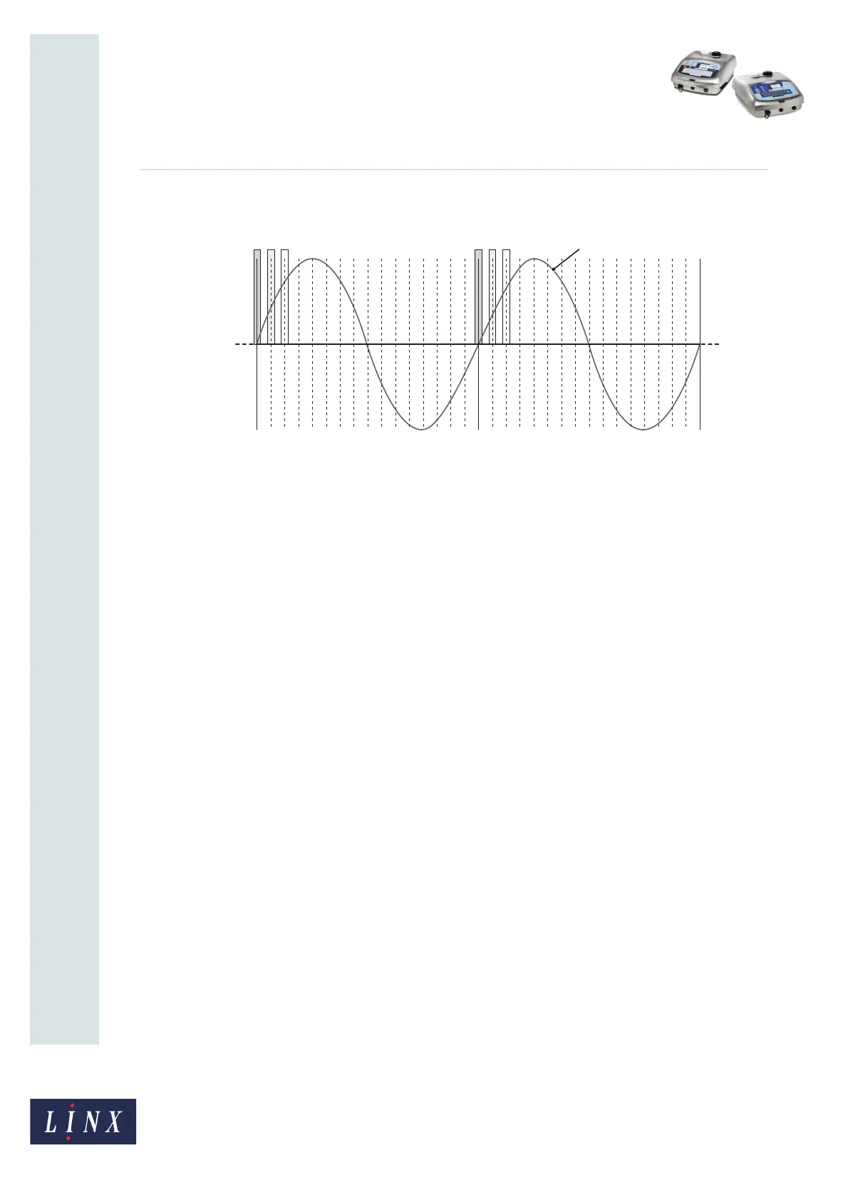
Figure 8 shows how a phase value is defined.
Figure 8. Phase values
The Modulation signal (D) and the Charge signal (A) are generated at the same frequency.
The Charge signal appears when the Modulation signal increases through zero volts (the
line “X … X”).
To adjust the charge on the ink drops, the printer can delay the Charge signal (for example
to B or to C). The delay (Phase value) depends on a number of factors, for example the ink
type and the temperature.
There are 16 possible phase values as shown in Figure 8. The phase value for Charge
signal A is 0, the value for signal B is 1, and the value for signal C is 2. The printer tries each
phase value to find the setting that gives the correct charge.
NOTE: The waveform and the pulses in Figure 8 are for example and are not accurate
illustrations of the signals in the printer.
The number shown for the Phase value is not important, but the value must not change
quickly or by a large amount. The number changes while the ink temperature increases
after you start the printer. After the printer has operated for a number of minutes, the Phase
value changes by only 1 or 2 in each minute of operation.
0 01
A
2
B
3
C
4567891011121314150123
ABC
456789101112131415
D
69257
X X