Page 9 of 25 FA69372–2 English
Jun 2013
25
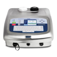
How To Install and Set Up the 5900 &
7900 Printer
Linx 5900 & 7900
3.1 Shaft encoder connection
You must use a 9-pin, D-type connector to connect the shaft encoder to the printer. The
following table describes the function of each pin.
Connect the screen of the shaft encoder cable to the shell of the connector. The connector
shell must connect to the printer chassis. Do not connect the screen to 0 volts.
To maintain the IP65 rating of the 7900 printer, the connector of the shaft encoder must have
an IP65 rating. Linx shaft encoders have a D-type connector that has an IP67 rating.
CAUTION: Use only Linx-approved accessories. The EMC performance of the printer can
change if you use other shaft encoders and cables.
3.1.1 Select the shaft encoder, encoder wheel, and Print Width
If you use a shaft encoder, you must perform the following calculations to calculate the
number of pulses per millimetre and the drop pitch. The calculations require a series of
steps as shown below:
1 Define the Required Raster Pitch.
2 Select the shaft encoder, the encoder wheel, and the Pitch Factor to get a raster pitch
that approximately equals the correct pitch.
3 Make sure that the calculated performance is acceptable (message length and print
speed).
4 Use the Pitch Factor to calculate the number of encoder pulses per millimetre. Enter
this value into the Speed page (Line Setup > Speed).
Calculate the raster pitch and use this value for the Print Width parameter (Print
Settings > Print Width).
5 Check the print samples for performance.
If you do not follow these calculation steps, your messages are not printed at the required
size. The spaces between the rasters are too small or too large.
Function Connection pin
+ 24 V Pin 1
0 V Pin 2
+ 5 V Pin 3
Single-ended input Pin 8
Figure 7. Shaft encoder pin connections