EasyManua.ls Logo

Lionel 313 - User Manual

Lionel 313
4 pages
Print Icon
To Next Page IconTo Next Page
Loading...
71-2948-250
05/98
LIONEL
®
Important notes on installation of your bascule bridge
Leave
1
/
16 clearance
between track and bridge
rails to prevent binding
U channel track alignment guide
Turn cam to lock
down track
For Point to Point layouts, track power will need to
be connected to both sides of the bridge, due to the
insulated section
Note!
Orient track pins in
this direction.
Moving section of
bridge rests on pins
Lionel 313 BASCULE BRIDGE
C
ongratulations on your purchase of the Lionel 313 bascule bridge. This classic Lionel
accessory has all the terrific action—and traditional quality—of the 1940-50 original. The
illuminated bascule bridge is made of die-cast metal and stamped steel construction and fea-
tures a powerful DC motor for years of reliable operation.
The bascule bridge can be placed in any Lionel O or O-27 three-rail layout, using the frame
provided and is designed to operate at 12-18 volts alternating current.
W
hen properly installed on your layout, activation of the bridge
causes the span to raise to approximately 45°. At the same time,
power to the insulated block leading in and out of the bridge is
removed automatically, to prevent trains from crossing the bridge
while in operation. A second activation lowers the bridge span and
reconnects the power to the insulated block allowing trains to proceed
safely across the bridge. In conventional layouts, the reversing unit
must be locked in forward for automatic train restart. In command
mode, it is necessary to restart your train using your Cab-1 remote. The
bulb inside the shed will light whenever power is on to the bridge. The
flashing warning light atop the bridge will operate only while the
bridge is moving or in the raised position. If the bridge is activated
while a train is on the span, a clutch mechanism is included to prevent
damage to the gearbox. The clutch mechanism consists of interlocking
“crowns” which are spring loaded. These will slip over each other in
event of an overload on the bridge.
The noise the clutch mechanism produces as it slips is loud,
do not be alarmed. No damage has occurred.
DO NOT deliberately activate the clutch. Overuse can lead to
premature wear of the mechanism.
Operation of your bascule bridge
Note!
Note!
F
or optimum bridge operation, its location on your layout should
be flat and level. Your bridge is assembled ready for
“O” gauge installation. It displaces two pieces of “O”
gauge straight track. To create the insulated block,
you will need to remove two center rail steel pins at the locations shown
below. There is a large “U” channel/bracket supplied to hold and
align the track at the base of the span(see Page 2 for installation).
Installation of your bascule bridge “O” gauge
Four track block sectionFour track block section
Use appropriate insulating pin for
center rail
Orient track pins in this direction.
Moving section of bridge rests on pins
Use three steel pins pro-
vided to assemble track to
bridge
Use appropriate
insulating pin for
center rail
Question and Answer IconNeed help?

Do you have a question about the Lionel 313 and is the answer not in the manual?

Summary

Operation of your bascule bridge

Important Notes on Bascule Bridge Installation

Track Alignment and Clearance

Ensures proper bridge operation by setting track clearance and pin orientation.

Installation of your bascule bridge “0” gauge

O Gauge Track Preparation

Details removing center rail pins and preparing track for O gauge installation.

Installation of your bascule bridge “027” gauge

O27 Gauge Track Preparation

Covers removing supports and using adapter pins for O27 gauge layouts.

Wiring your bascule bridge for conventional operation

Conventional Wiring Methods

Explains wiring for track power or separate supply using switches or contactors.

Wiring your bascule bridge to an SC-1

SC-1 Control Wiring

Details connecting the bridge to an SC-1 controller via spring clips for remote activation.

Travel Adjustment for Bridge Operation

Adjusting Lower Travel Limit

Guides adjustment of the stop switch to ensure the bridge lowers correctly.

Adjusting Raise Travel Limit

Guides adjustment of the stop switch to prevent clutch activation when raising.

Replacing Lamps and Service Information

Lamp Replacement Procedure

Instructions for replacing the illuminated lamps in the bridge's shed and warning light.

Lionel Service and Warranty

Details obtaining service, warranty claims, and product registration.

Overview

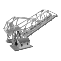
The Lionel 313 Bascule Bridge is a classic Lionel accessory designed to add dynamic action to O or O-27 three-rail layouts. It features a die-cast metal and stamped steel construction, ensuring durability and a traditional aesthetic reminiscent of 1940-50 originals. The bridge is illuminated and powered by a robust DC motor, engineered for years of reliable operation. It is designed to operate with 12-18 volts alternating current.

Function Description:

The primary function of the bascule bridge is to raise and lower its span, simulating a real-world bascule bridge. When activated, the bridge span raises to approximately a 45° angle. Concurrently, power to the insulated track block leading into and out of the bridge is automatically removed, preventing trains from crossing while the bridge is in motion. A second activation lowers the bridge span and restores power to the insulated block, allowing trains to safely proceed.

The bridge includes an illuminated shed and a flashing warning light atop the bridge. The shed light is active whenever power is supplied to the bridge, while the flashing warning light operates only when the bridge is moving or in its raised position.

Important Technical Specifications:

  • Power Requirement: 12-18 volts alternating current (vac).
  • Motor: Powerful DC motor.
  • Construction: Die-cast metal and stamped steel.
  • Track Compatibility: Lionel O and O-27 three-rail layouts.
  • Insulated Track Block: Automatically cuts power to track sections when the bridge is raised or moving.
  • Clutch Mechanism: Prevents damage to the gearbox if the bridge is activated while a train is on the span. This mechanism consists of interlocking, spring-loaded "crowns" that slip over each other under overload conditions. Users are advised not to deliberately activate the clutch, as overuse can lead to premature wear.
  • Lamps: Two 18-volt lamps (Lionel part #20-2972-300) for illumination in the shed and as a flashing warning light.

Usage Features:

  • Conventional Operation:
    • The bridge can be powered by track power or a separate accessory power supply.
    • It can be operated using the included momentary switch (190-001).
    • For automatic activation, a 153C contactor or an insulated track section (sold separately) can be used.
    • Variable voltage control is recommended for adjusting the bridge's speed of operation.
    • For conventional layouts, the reversing unit of the train must be locked in forward for automatic train restart after the bridge lowers.
    • The Lionel 3 amp controller (part no. 01-2885-000) is recommended as an ideal power source.
  • Command Control Operation (with SC-1):
    • The bridge can be connected to an SC-1 command control unit.
    • After assigning an accessory number to the SC-1, users can activate the bridge's drive motor by pressing AUX1 on their CAB-1 remote.
    • In command mode, trains need to be restarted using the Cab-1 remote after the bridge lowers.
  • Track Installation:
    • The bridge requires a flat and level surface for optimum operation.
    • For "O" gauge layouts, it displaces two pieces of "O" gauge straight track. Two center rail steel pins need to be removed to create the insulated block.
    • For "027" gauge layouts, six mounting supports under the bridge base must be removed. Three adapter pins and "027" gauge insulating pins are installed. A 2¼" length of 027 track may need to be cut to compensate for the bridge's length in closed-loop layouts.
    • A "U" channel/bracket is supplied to secure and align the track at the base of the span.
    • A 1/16" clearance between track and bridge rails is crucial to prevent binding.
    • Track pins should be oriented in a specific direction, with the moving section of the bridge resting on the pins.
    • A cam mechanism is used to lock down the track.
  • Travel Adjustment:
    • Lowering Adjustment: If the bridge does not lower completely or rest on the pins, the internal stop switch needs adjustment. This involves removing the cap on the pivot point (shed side) and turning the adjustment screw counter-clockwise 1/4 turn at a time. The cap should be held in place while running the bridge to verify the adjustment.
    • Raising Adjustment: If the bridge lowers but does not switch off before the clutch activates, the stop position needs adjustment. This involves removing the cap and turning the adjustment screw clockwise 1/4 turn at a time. The cap should be held in place while running the bridge to verify the adjustment.

Maintenance Features:

  • Lamp Replacement:
    • The bridge uses two 18-volt lamps (Lionel part #20-2972-300).
    • To replace the lamp in the shed, slide the roof off, unscrew the old lamp, and install a new one.
    • To replace the warning lamp on the bridge, unscrew the red lens, then unscrew the old lamp and install a new one.
  • Warranty: Lionel products, including mechanical and electrical components, are warranted for the original consumer-purchaser's life against original defects in materials or workmanship when purchased through an authorized Lionel merchant. This warranty does not cover normal wear and tear, light bulbs, defects from commercial use, abuse, or misuse. Warranty service involves repair or replacement at no charge for parts or labor. Products must be sent freight or postage prepaid.
  • Service: For service, contact an Authorized Lionel Service Center or Lionel L.L.C. directly. A return authorization letter and label are required for factory repairs. Products should be securely packed, preferably in original packaging, and insured.

Lionel 313 Specifications

General IconGeneral
BrandLionel
Model313
CategoryToy
LanguageEnglish

Related product manuals