Y
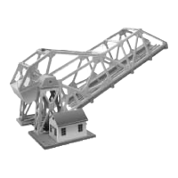
our bridge will operate best from 12 to 18 vac. It can be powered with
track power or a separate accessory power supply. It is possible to oper-
ate your bascule bridge any number of ways. Your bridge will operate using
an SC-1 (command control), or using the included momentary switch. It is
also possible to automatically activate the bridge using a 153C contactor or
insulated track section (sold separately). Variable voltage control is recom-
mended so you can adjust the bridge speed of operation to your liking.
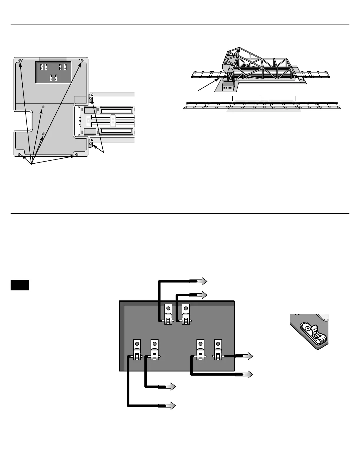
Connect two insulated wires (included) from 190-001 switch (included) to
the spring clips on the bascule bridge as shown in the diagram below. To
connect the wires to the spring clips, press down the springy upper half of
the metal loop until the lower part projects through the slot. Insert the bare
wire end into the loop, and release the upper part of the clip. Spring tension
will hold the wire tight. To operate your bascule bridge using the switch, just
push the botton and enjoy being the bridge-master
Wiring your bascule bridge for conventional operation
To switch: 190-001 included, or a insulated
track section, or 153c contactor sold separately
To center rail clip on U channel
To center rail outside block or “A”
TRACK POWER transformer terminal
To “U” terminal of track power
supply (if using track power) or
accessory power supply
To “A” terminal of track power
supply (if using track power)
or accessory power supply
2
2
We recommend the Lionel 3 amp
controller part no. 01-2885-000 as an
ideal power source for this accessory
Note!
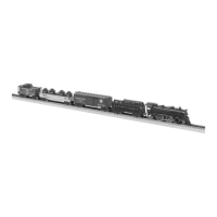
F
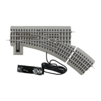
or “027” gauge layouts, first remove the six mounting supports
under the base of the bridge.(see illustration below) Install the
three adapter pins and “027” gauge insulating pins as above. For
closed loop layouts, a piece of 027 track cut to 2
1
/
4” length will be
required to compensate for the length of the bridge.
Installation of your bascule bridge “O27” gauge
“U” channel provided to secure and
align track, slips over pins on base of
bridge
For “027” gauge layouts, remove
these mounting supports
027 to 0 gauge adapter pins
Two, 027 track sections plus one 2
1
/4
” cut piece