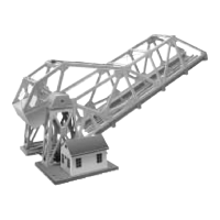
I
f the bridge lowers and does not switch off before the clutch acti-
vates, make this adjustment. First remove the four screws holding
the cap on the pivot point of the bridge (shed side). Remove the cap.
To RAISE the stop position, turn the adjustment screw clockwise 1/4
turn at a time. HOLD THE CAP IN PLACE when running the bridge
to verify your adjustment
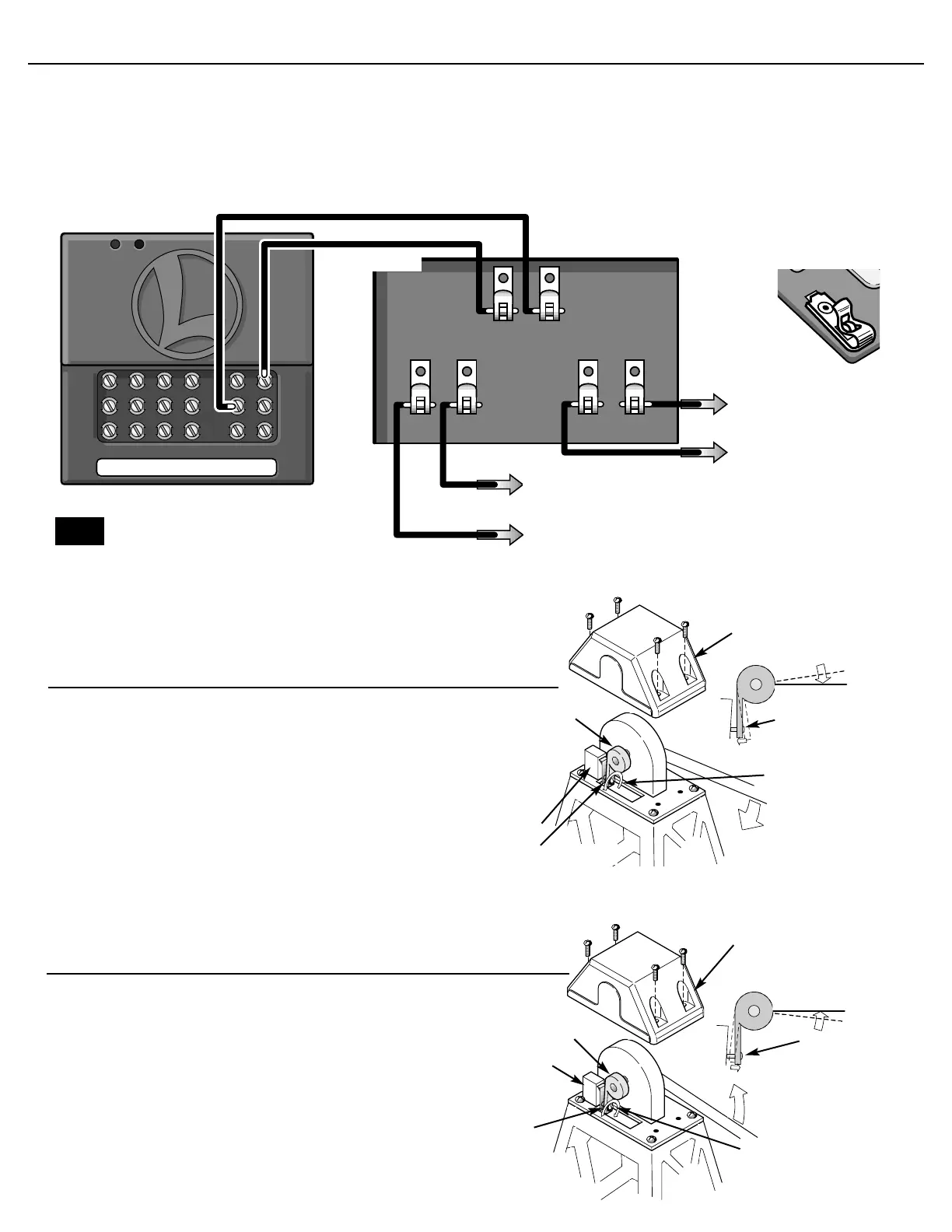
Travel adjustment to raise the bascule bridge
cap
cam
Adjustment
screw
Stop switch
Turn adjustment
screw clockwise
1/4 turn at a time
Adjustment
screw
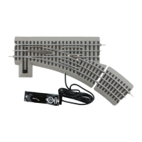
C
onnect two insulated wires (included) from the SC-1 to the spring
clips on the bascule bridge as shown in the diagram below. To con-
nect the wires to the spring clips, press down the springy upper half of
the metal loop until the lower part projects through the slot. Insert the
bare wire end into the loop, and release the upper part of the clip.
Spring tension will hold the wire tight. When all the connections have
been made, plug your SC-1’s wall pack into a standard outlet. To oper-
ate your bascule bridge using the SC-1, you must first assign it an acces-
sory number (refer to your SC-1 instruction manual).
After the number has been assigned, press AUX1 on your CAB-1
remote to activate the bascule bridge’s drive motor.
Wiring your bascule bridge to an SC-1
To center rail clip on U channel
To SC-1 AUX-1
To SC-1 COMMON
To center rail outside block
or “A” TRACK POWER
transformer terminal
To “U” terminal of accessory
power supply
To “A” terminal of accessory
power supply
If using common ground, make sure
power supplies are in phase
3
3
Note!
N
ote If you are installing your bridge on an “027” gauge layout,
it may be necessary to adjust the bridge’s internal stop switch.
If the bridge does not lower all the way and is not resting on the
pins, make this adjustment. First remove the four screws holding
the cap on the pivot point of the bridge (shed side). Remove the
cap. To LOWER the stop position, turn the adjustment screw
counter clockwise 1/4 turn at a time. HOLD THE CAP IN PLACE
when running the bridge to verify your adjustment
Travel adjustment to lower the bascule bridge
Adjustment screw
Stop switch
Turn adjustment
screw counter
clockwise 1/4
turn at a time
cam
cap
Adjustment
screw