2
Table of contents
Transformer operations
Running your SD-90 with a Lionel transformer 3
Locking your SD-90 into a single operational state 4
Using your SD-90 ElectroCoupler in the non-command environment 5
Installing the Lionel no. 610-5906-001 sound activation button 6
Maintaining and servicing your SD-90
Lubricating your SD-90 7
Adding fluid to your Locomotive’s smoke generator 8
Replacing your SD-90’s lamps 8-9
Odyssey™ System operations
Odyssey™ System operations 10
TrainMaster
®
Command operations
Your SD-90’s RailSounds
™
system—the basics 11
Experiencing the range of your SD-90’s RailSounds
™
system 12
The Command
™
control environment 13
Running your SD-90 in the TrainMaster
®
Command environment 14
CAB-1 numeric keypad commands for your SD-90 15
Tuning your SD-90’s performance 16
Assigning your SD-90 a new ID# 17
Reprogramming R2LC circuit boards to restore or change features 18
Notes 19
Lionel Service 20
• Odyssey
TM
System Speed Control
• Two powerful flywheel equipped
can motors
• Digital TrainMaster Command
™
controlled
• RailSounds
TM
digital — sound system
• Tire-Traction
• Die-cast ElectroCouplers
• Illuminated headlights/rear light/
interior light
• CrewTalk (in command)
• TowerCom (in command)
• Diesel smoke generator
• Directional lighting
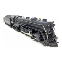
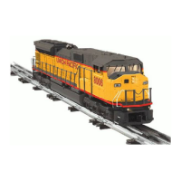
Y
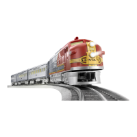
ou purchased a tough, durable loco-
motive—the SD-90 diesel locomotive
built by Lionel. From the crisp detail and
expert decoration on the outside to the brute
power under the hood, the Lionel SD-90 is
ready for duty on your model railroad.
Experience the superiority of today’s Lionel.
Congratulations!
IMPORTANT NOTICE (Please Read First)
In order to allow maximum play value of the SD-90 engine, it has been designed to run on
track as little as 0-31 radius. However, due to the immense scale length of the SD-90 the older
switches (5132, 5133) must have the Lantern Housing “Set” on the outside location of the
turnout to allow proper operation. Please refer to your O-gauge switch instruction sheet for
changing the orientation.
NOTE: Newer O-gauge Switch (P/N 612-3010-000, 612-3011-000) allow for better clearnace in
both locations and will not encounter any interference.
 Loading...