4
lci1.com 574-537-8900 Rev: 03.06.20
Power Tongue Jack
Installation and Owner’s Manual
(For Aftermarket Applications)
CCD-0001301
Installation
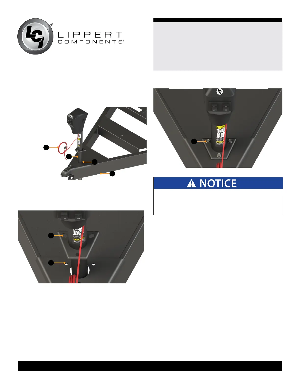
1. Carefully slide the jack leg (Fig.2B) through the hole in
the coupler (Fig.2C) on the trailer A-frame (Fig.2D).
ALL ELECTRICAL WIRING HARNESSES SHALL BE
LOOMED AND SECURED TO PREVENT POSSIBLE
DAMAGE AND INSTALLED IN ACCORDANCE WITH
RVIA ELECTRICAL STANDARDS.
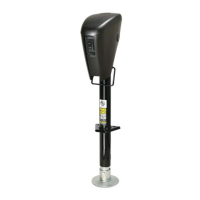
2. Align the three holes in the Power Tongue Jack
mounting plate (Fig.3A) with the three holes in the
coupler (Fig.3B).
Fig.2
Fig.3
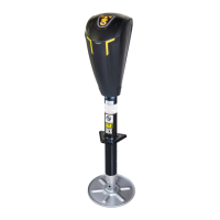
3. Secure the Power Tongue Jack to the coupler plate with
the three provided 3/8” - 16 x 1” hex bolts (Fig.4A).
4. Connect the red power wire from the Power Tongue
Jack housing to a grounded 12V power supply on the
trailer.
5. The Power Tongue Jack must be wired through a 30
amp fused circuit.
6. Loom the harness wires (Fig.2A) with the appropriate
size and length to protect the wires from damage.
7. Reattach the footpad to the jack leg by sliding the
footpad back over the bottom of the jack leg and securing
it with the clevis pin and hairpin cotter pin previously
removed (Fig.1).
Fig.4
B
C
A
B
A
A
D