EasyManua.ls Logo

Lippert Components IN-WALL - User Manual

Lippert Components IN-WALL
2 pages
Print Icon
To Next Page IconTo Next Page
Loading...
Rev: 09.09.20 Page 1 FR
IN-WALL
®
SLIDE-OUT TROUBLESHOOTING
Troubleshooting
Error Codes
During operation when an error occurs, the board will use the LEDs to indicate where the problem exists.
The green LED will blink once for Motor 1, and two times for Motor 2. The red LED will blink from two to
nine times, depending on the error code. The error codes are as follows:
Manual Override
In the event of any error code, the system can be manually overridden electronically using these steps:
1. Locate the controller.
2. Press the “mode button” six times quickly, press a seventh time and hold for approximately five
seconds.
3. The red and green LED lights will begin to flash indicating the system is in override mode.
4. Using the wall switch, press and hold the IN button until the room comes completely in.
NOTE: The "8" error code is the most common. This can signify one of these issues:
Pinched or broken wiring in the system harness or motor pigtail.
Disconnected or faulty motor.
Checking Fuses
Check the 12 volt fuse box for blown fuses, and replace any if necessary. If the fuse blows immediately upon
replacement, there is a problem with the wiring to the circuit board. Have qualified service personnel check
and repair.
Obstructions
Check outside the unit for possible obstructions: tree, post, car, folded over flap seals, debris on top of the
slide room, etc. Check inside the unit for any obstructions: luggage, furniture, open cabinets, carpeting,
wiper seal, etc. Also check for smaller objects that may be wedged under the floor or in the sides of unit.
Remove obstructions before proceeding.
LED Error Code Error Code Concern
2 Battery drop out: Battery capacity low enough to drop below 6 volts while running.
3 Low battery: Voltage below 8 volts at start of cycle.
4 High battery: Voltage greater than 18 volts.
5 Excessive motor current: High amperage, caused by an obstruction.
6 Motor short circuit: Motor or wiring to motor has shorted out.
8
Wire short between controller and motor: Encoder is not providing a signal.
Usually a wiring problem.
9
Hall power short to ground: Power to encoder has been shorted to ground.
Usually a wiring problem.
Question and Answer IconNeed help?

Do you have a question about the Lippert Components IN-WALL and is the answer not in the manual?

Summary

Troubleshooting

Error Code Diagnostics

Details LED error codes and their associated problems for diagnosis.

Manual System Override

Provides steps for electronically overriding the system in case of errors.

Fuse and Obstruction Checks

Instructions for checking fuses and removing physical obstructions.

Low Voltage Operation

Slide-Out Movement Issues

General Checks: Debris, LEDs, Connections

Covers checks for debris, status LEDs, and power/ground connections.

Overview

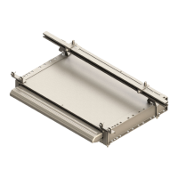
This document outlines troubleshooting procedures for the Lippert Components IN-WALL® Slide-Out System, a device designed to extend and retract a room within a larger unit, likely a recreational vehicle (RV) or similar mobile structure. The system uses electric motors to operate the slide-out room and incorporates a controller with LED indicators to communicate operational status and error conditions.

Function Description

The IN-WALL® Slide-Out System facilitates the extension and retraction of a room section, providing additional living space when deployed. It operates using two separate motors, one for each side of the room, ensuring synchronized movement. The system is controlled via a wall switch, allowing users to extend or retract the room as needed. A central controller manages motor operations, monitors system health, and provides diagnostic feedback through LED error codes.

Important Technical Specifications

  • Operating Voltage: The slide-out controller is capable of operating with as little as 8 volts. However, lower voltages increase amperage requirements. Optimal operation is achieved with higher voltage, and it is recommended to charge the battery if the voltage drops below 11 volts. The system can handle a high battery voltage of up to 18 volts.
  • Motor Configuration: The system employs two independent motors, one for each side of the slide-out room, to ensure balanced and smooth movement.
  • Error Indication: The controller uses a combination of green and red LEDs to signal error conditions. The green LED blinks once for Motor 1 and twice for Motor 2. The red LED blinks from two to nine times, corresponding to specific error codes.
  • Manual Override: The system includes an electronic manual override function, activated by a specific sequence of button presses on the controller. This allows for manual retraction of the room even when an error code is present.
  • Power Source: The system operates on a 12-volt power supply, typically from a battery.

Usage Features

  • Standard Operation: The room is extended or retracted using a wall switch. Users press and hold the appropriate button (IN or OUT) until the room is fully in or out.
  • Error Code Diagnostics: The LED error codes provide specific information about potential issues, allowing users or technicians to identify the problem quickly.
    • LED Error Code 2 (Red Blinks 2x): Battery drop out – battery capacity low enough to drop below 6 volts while running.
    • LED Error Code 3 (Red Blinks 3x): Low battery – voltage below 8 volts at the start of a cycle.
    • LED Error Code 4 (Red Blinks 4x): High battery – voltage greater than 18 volts.
    • LED Error Code 5 (Red Blinks 5x): Excessive motor current – high amperage, often caused by an obstruction.
    • LED Error Code 6 (Red Blinks 6x): Motor short circuit – motor or wiring to motor has shorted out.
    • LED Error Code 8 (Red Blinks 8x): Wire short between controller and motor – encoder is not providing a signal, usually a wiring problem. This is noted as the most common error code and can indicate pinched/broken wiring or a disconnected/faulty motor.
    • LED Error Code 9 (Red Blinks 9x): Hall power short to ground – power to the encoder has been shorted to ground, usually a wiring problem.
  • Electronic Manual Override: In case of an error, the system can be electronically overridden. This involves locating the controller, pressing the "mode button" six times quickly, then pressing it a seventh time and holding for approximately five seconds. The LEDs will flash, indicating override mode, after which the wall switch can be used to retract the room.
  • Addressing One-Side Movement: If only one side of the room moves a short distance and stops, the manual suggests assisting the non-moving side by pushing it in the appropriate direction while simultaneously operating the wall switch. For larger rooms, multiple people may be required. If a motor shaft is broken, it might be possible to manually push the side of the room several inches. Disengaging the motor and attempting to move the room by hand is also suggested.

Maintenance Features

  • Fuse Checking: Regular inspection of the 12-volt fuse box for blown fuses is crucial. Blown fuses should be replaced. If a fuse blows immediately after replacement, it indicates a wiring problem to the circuit board, requiring professional service.
  • Obstruction Removal: Before operating the slide-out, it is essential to check for and remove any obstructions both outside and inside the unit. External obstructions can include trees, posts, cars, folded-over flap seals, or debris on top of the slide room. Internal obstructions can include luggage, furniture, open cabinets, carpeting, or wiper seals. Smaller objects wedged under the floor or in the sides of the unit should also be checked.
  • Low Voltage Management: If the battery voltage is below 11 volts, it is recommended to place the battery on a charger until it is fully charged. While it may be possible to "jump" the unit battery temporarily, a WARNING explicitly states never to jump or charge the battery from the power connections on the In-Wall® controller, but always directly at the battery to prevent serious injury.
  • Debris Inspection (Gear Racks): Periodically check all gear racks on the side of the room for debris. Also, inspect for obstructions like wiper seals caught in the floor or v-rollers.
  • Status LED Monitoring: When actuating the slide extend/retract switch, observe if the status LEDs light up in both extend and retract modes. If they do not, or only light in one direction, unplug and re-plug the extend and retract wire connection on the board. Persistent issues may indicate a defective switch or wiring.
  • Power and Ground Connections: Ensure all power and ground connections are clean, tight, and free of corrosion to maintain reliable operation.
  • Obstructions (General): The document provides a comprehensive list of potential obstructions to check for, including tree branches, posts, cars, folded-over flap seals, debris on top of the slide room, luggage, furniture, open cabinets, carpeting, wiper seals, and smaller objects wedged under the floor or in the sides of the unit. Removing these is critical for proper function.

Lippert Components IN-WALL Specifications

General IconGeneral
BrandLippert Components
ModelIN-WALL
CategoryBicycle
LanguageEnglish

Related product manuals