The provided document is a service manual for the IN-WALL® Slide-out System, manufactured by Lippert Components. This system is designed for recreational vehicles (RVs) to extend and retract slide-out rooms, enhancing living space. The manual emphasizes safety, operation, troubleshooting, and maintenance procedures for the system.
Function Description
The IN-WALL® Slide-out System's primary function is to actuate (extend and retract) slide-out rooms in RVs. It utilizes a dual-motor synchronous velocity slide controller to ensure smooth and synchronized movement of the slide-out room. The system is designed to operate within a 12V DC input range, typically from 8V DC to 18V DC, and requires a minimum 30-amp circuit breaker for power. The controller manages two motors, ensuring they work in unison to prevent binding or uneven movement of the slide-out room.
Usage Features
Operation:
To operate the slide-out, the RV must be parked on a solid and level surface, and the leveling or stabilizing system should be actuated. For motorized units, the ignition must be off. Users must ensure all persons and pets are clear of the slide-out path and keep hands away from the mechanisms. Transit bars, if equipped, should be removed before extension and reinstalled after retraction.
Extending and Retracting the Slide-out Room:
The process involves pressing and holding an IN/OUT switch. To extend, hold the switch in the "OUT" position until the room is fully extended and the motors shut off automatically after a few seconds. Similarly, to retract, hold the switch in the "IN" position until the room is fully retracted and the motors shut off. Releasing the switch locks the room in position.
Electronic Manual Override (Controllers C-1 and C-2 Only):
In case of an issue, a manual override mode can be engaged by pressing the "mode button" on the controller six times and holding it on the seventh press for five seconds. The red and green LEDs will flash to indicate override mode. In this mode, the extend/retract switch can be used to move both motors. Over-current and short-circuit detection remain active. To exit, hold the mode button until the LEDs blink simultaneously, which resets motor positions and requires resynchronization. This mode allows for individual motor movement, which means the room may not move synchronously, requiring careful visual monitoring.
Motor Direction Switches:
The controller features motor direction switches (one for each motor) that allow users to change the direction of individual motors. This is useful if one side of the room moves in the wrong direction during extension or retraction. These switches can also reverse the overall extend/retract switch direction if needed, offering flexibility in wiring configurations.
Maintenance Features
Visual Inspections:
Regular visual inspections are crucial for maintaining the system. This includes checking for obstructions outside and inside the RV, such as trees, furniture, or debris. Users should also inspect the gear racks for dirt, debris, or metal shavings that could cause binding and clean them with compressed air or a dry brush.
Measurements:
Key measurements should be taken to ensure proper alignment. The distance from the outside edge of the column to the face of the gear rack should be 2 ½" plus or minus ⅛" when fully extended and when 3" from fully retracted. Gear racks must be parallel, with less than ⅛" difference between parallel measurements. Proper seal engagement (¼" nominal overlap) and absence of damage to the gear rack should also be verified.
Floor Rollers and V-Rollers:
Inspect floor rollers to ensure seals are not caught, rollers are not digging into the slide-out floor, and they do not spin freely. V-rollers should be visually inspected for obstructions or damage.
Troubleshooting (Error Codes):
The controller provides diagnostic error codes through blinking LEDs (green for motor identification, red for error type). For example, a green LED blinking once indicates motor 1, twice for motor 2. Red LED blinks indicate specific faults like battery dropout, low/high battery voltage, excessive motor current, motor short circuit, or hall signal issues. Resetting the board by energizing the extend/retract switch is required after an error.
Checking Circuit Breakers:
The system requires a 30-amp circuit breaker. Users should check the 12-volt circuit breaker box for blown breakers and replace them as needed. If a breaker blows immediately, it indicates a wiring problem that requires professional service.
Low Voltage:
The system can operate with as little as 8 volts, but lower voltages increase amperage requirements. Checking voltage at the controller is recommended. If the battery is low, it should be charged, or the unit should be plugged into shore power or a generator. Temporarily "jumping" the RV's battery may be possible, but connections should always be made directly to the battery, not the controller's power connections.
Resynchronizing the Slide-out Motors:
If motors become unsynchronized, the procedure involves fully extending the room, holding the switch until motors shut down, retracting 1-2 inches, and repeating these steps until both motors shut down simultaneously at full extension and retraction. This process may require multiple repetitions.
Motor Disengagement Procedure:
To disengage a motor, remove retention screws located near the top of each vertical column on the outside of the coach (under the bulb seal). For units prior to 2011, bend back the wipe seal; for 2011 and later, locate the slot in the H-column. Pull the motor up approximately ½" until disengaged, using a flat-head screwdriver if necessary. Reinstall the retention screw or remove the motor.
Motor Replacement:
Motor replacement requires access to both the interior and exterior of the coach. The slide-out room should be extended halfway. Procedures vary slightly for "current style" motors with a notch and "old style" motors without a notch. Both involve removing seals, retention screws, and disconnecting wiring harnesses. When installing a new motor, it's crucial to align the drive shaft with the coupler in the bearing block. Fast-bonding adhesive is used to secure the wipe seal.
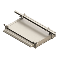
Assembly Removal and Installation:
The manual details procedures for removing and installing the entire slide-out assembly. Removal may involve using electronic override, disconnecting motor harnesses, or disengaging motors. Tools like a rubber mallet, 2x4 block, razor knife, and floor jack are recommended. Installation involves cleaning surfaces, applying sealant, carefully slipping the assembly into the opening, aligning gear racks, and securing them with screws. Proper alignment and synchronization of motors are critical after installation.