Rev: 06.14.2016
Page 5
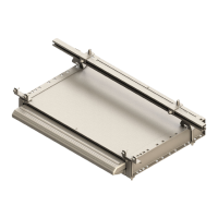
IN-WALL® Slide-out Service Manual
Controller Version
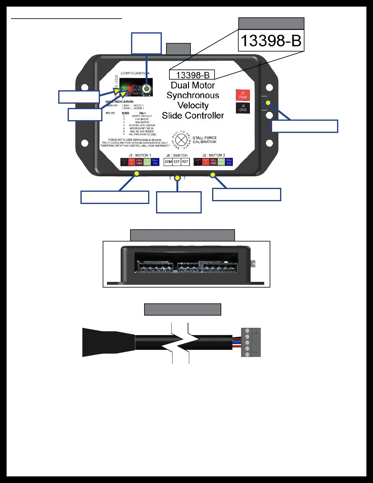
Controller Overview (B Version)
Status LEDs: 2 LEDs, 1 green and 1 red, are provided to indicate current controller status and faults.
Power Connection: 12V DC input. Unit will operate from 8V DC to 18V DC.
Switch Connection: Spade connection for the switch wiring.
Motor 1 Connector: Power and encoder input for motor 1.
Motor 2 Connector: Power and encoder input for motor 2.
NOTE: Version B motor harnesses have five wire in-line connectors at the controller and the molded
connector at the motor end (Figs. 3 and 4). Wire colors match with color codes on control board. It
does not matter which motor is 1 or 2.
Fig. 2
Switch
Connection
Mode
Button
Fig. 3 - Controller Connections
Fig. 4 - Motor Harness
Green LED
Red LED
Motor 1 Connector
Motor 2 Connector
Power Connection