Rev: 06.14.2016
Page 8
IN-WALL® Slide-out Service Manual
Motors and Harnesses
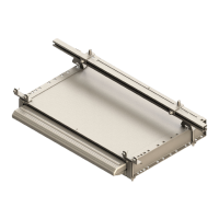
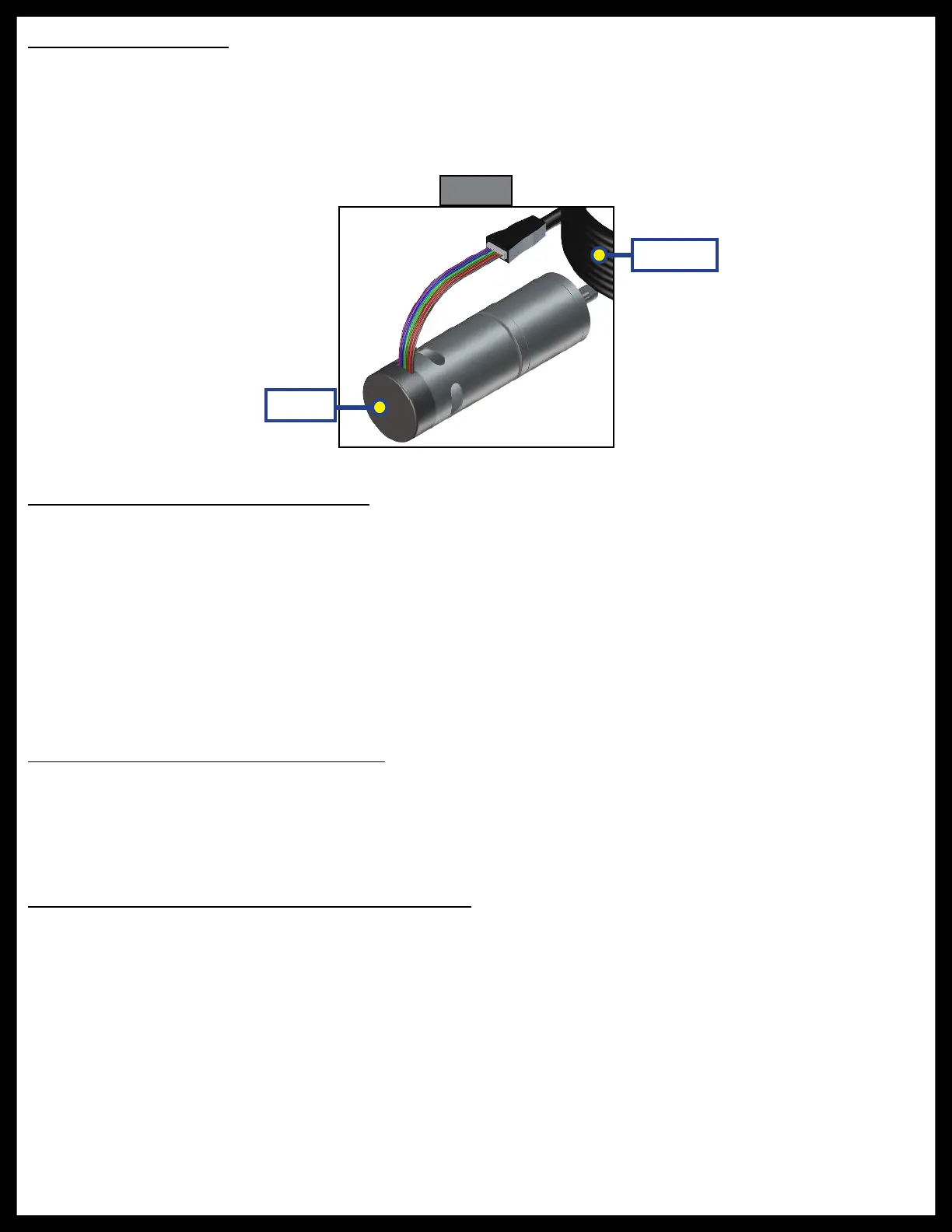
1. Check for proper connections between the motors and harnesses (Fig. 17).
2. Visually inspect the exposed harnesses to ensure they are not pinched or damaged.
NOTE: Ribs on motor connector line up with notch inside of female connector on wiring harness. Color
codes on wires also match (black to black, red to red, etc.)
Resynchronizing the Slide-out Motors
1. Fully extend the slide room using the switch. Keep the switch engaged until the motors shut down on
their own.
2. Retract the room 1-2 inches.
3. Repeat steps 1 and 2 until both motors shut down at the same time. In many cases, two or three
repetitions are necessary to re-sync the system.
4. Fully extend the slide-out and keep the switch engaged until the motors shut down on their own.
Fully retract the slide-out, again keeping the switch engaged until the motors shut down on their own.
If both motors shut down at the same time at full extension and full retraction, the room is properly
synchronized. If they do not shut down at the same time, repeat the process until they do.
Extend and Retract Switch Connections
Rev. A - Rev. C1 Controllers: Common connection on controller goes to common connection on extend and retract
switch.
Rev. C2 and 8 amp Controllers: Extend and retract connections on the controller go to the extend and retract
terminals on the switch. Switch is powered by the OEM supplied 12V DC power source.
Power and Ground Connections at the Controller
Power and ground are supplied to the controller through the spade terminals located on the right-hand side
of the controller (Figs. 2 and 5 - Power Connection). 12V DC is recommended. A 10ga wire is the minimum size
recommended. A 30 amp resetting or blade fuse is required (OEM supplied).
Fig. 17
Motor
Harness

 Loading...