EasyManua.ls Logo

Lippert Components COACH STEP - User Manual

Lippert Components COACH STEP
4 pages
Print Icon
To Next Page IconTo Next Page
Loading...
LIPPERTCOMPONENTS, INC.
COACH STEP
INSTALLATION, OPERATION AND SERVICE MANUAL
AUTOMATIC ELECTRIC STEPS AND AUTOMATIC ELECTRIC SLIDING STEPS
FOR
RECREATIONAL VEHICLES
INSTALLATION PREP
WARNING!
Keep clear of steps as they are deployed. Step actuation takes approximately two seconds whether extending or retracting.
Keep hands and fingers away from step mechanism during actuation process to prevent serious bodily injury.
TEST PROCEDURE PRIOR TO INSTALLATION
1. Steps will install easier when extended first. Place steps upside down on workbench or floor.
2. Cut and connect four (4) jumper wires to the 4-pin connector. Match the jumper wires to the posts on the connector color for color.
3. Connect GREEN WIRE to the NEGATIVE post of a fully charged, 12V automotive battery.
4. Connect RED and WHITE WIRES to the POSITIVE post of the battery.
5. Connect the BROWN WIRE to the NEGATIVE post of the battery.
WARNING!
Steps will extend immediately!
6. Disconnect jumper wires from the battery.
INSTALLATION
Steps must be installed using four (4) 5/16”, GR 8 bolts, lock washer and nuts for the Automatic Elctric Steps and 3/8” bolts, lock washers and
nuts for the Automatic Electric Slideing Step. Retract steps by attaching wires in the following sequence:
1. Ground the GREEN WIRE to the chassis.
2. Touch the RED and WHITE wires to the positive terminal on the battery.
WARNING!
Keep clear of the steps as they will retract quickly.
Proceed to install door switch and power switch(items not included). The wires of the four pin connector must be routed as follows:
1. WHITE - Connect to power switch (16 ga. min. wire).
2. YELLOW - Must be connected to power source that is only hot when ignition is “ON.” Protect with 6A fuse or breaker (16 ga. min. wire).
3. RED - Connec to power for motor. Protect with 25A fuse (10 ga. min. wire).
4. BROWN - Connect to door switch (16 ga. min. wire).
3
2
1
4
Fig. 1
Question and Answer IconNeed help?

Do you have a question about the Lippert Components COACH STEP and is the answer not in the manual?

Lippert Components COACH STEP Specifications

General IconGeneral
BrandLippert Components
ModelCOACH STEP
CategoryAutomobile Accessories
LanguageEnglish

Summary

Installation Preparation and Testing

Installation Prep and Warnings

Keep clear of steps during deployment and retraction. Keep hands away from mechanism to prevent injury.

Test Procedure Prior to Installation

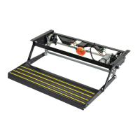
Steps for testing the automatic electric steps prior to mounting on the vehicle.

Installation Wiring Sequence

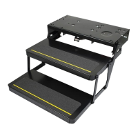
Steps for retracting steps and wiring connections for the four-pin connector.

Door Switch Installation and Operation

Door Switch Installation Guidelines

Recommendations for mounting the door switch and magnet for proper step actuation.

Step Operation - Power ON

Procedure for operating steps when power is on, including door opening and step extension.

Step Operation and Troubleshooting

Step Operation - Power OFF

Describes step behavior with power off, ignition on/off, and door open/closed.

Troubleshooting the System

Diagnostic steps for electrical and mechanical issues using a voltmeter.

Service Notes and Recommendations

Bolt Tightening and Torque

Recommendation to use Loctite on bolts and specifies torque for joint shoulder bolts.

Cam Adjustment Procedure

Guidance on adjusting cams for step arm locking, warning about excessive movement.

Installation Precautions

Recommends using bolts and flange nuts, advises against welding the step to the vehicle.

Motor and Module Service

Instructions for servicing the motor/gear assembly and replacing the module.

Lubrication and Contact Information

Notes on self-lubricating bushings and contact for service or warranty.

Related product manuals