Rev: 06.14.2016
Page 13
IN-WALL® Slide-out Service Manual
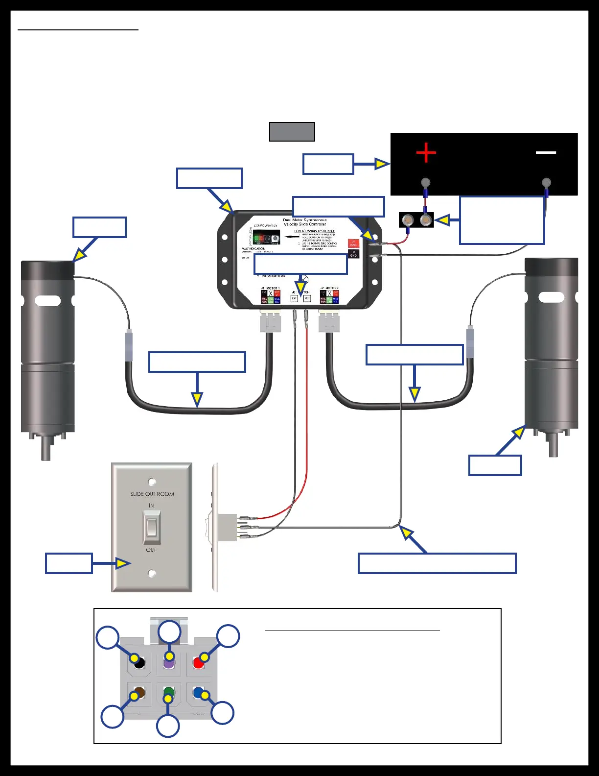
Wiring Color Code Information
A. Black - Power/Ground
B. Purple - Not Used
C. Red - Power/Ground
D. Brown - Hall Effect Power
E. Green - Hall Effect Ground
F. Blue - Hall Effect Communications
C
A
B
E
D
F
Rewiring Instructions
If it is necessary to replace a malfunctioning Rev. B, C, or C1 controller, it is recommended that the customer
do so with a new Rev. C2 controller. In order to properly rewire a Rev. B, C, or C1 controller to a new Rev. C2
controller, the customer will need two new motor harnesses (one for each motor.) Additionally, it will be
necessary to modify the power wire from the controller to the extend/retract switch by adapting the wire to
piggyback the connection at the power junction. This wire comes from the positive side of the buss bar to
the controller (Fig. 25).
Fig. 25
Power Junction
Modified Switch Power Wire
Switch Junction
Battery
OEM Supplied
Circuit
Interruption
Motor 1
Motor 1 Harness
Motor 2 Harness
Motor 2
Controller
Switch

 Loading...