Rev: 06.14.2016
Page 12
IN-WALL® Slide-out Service Manual
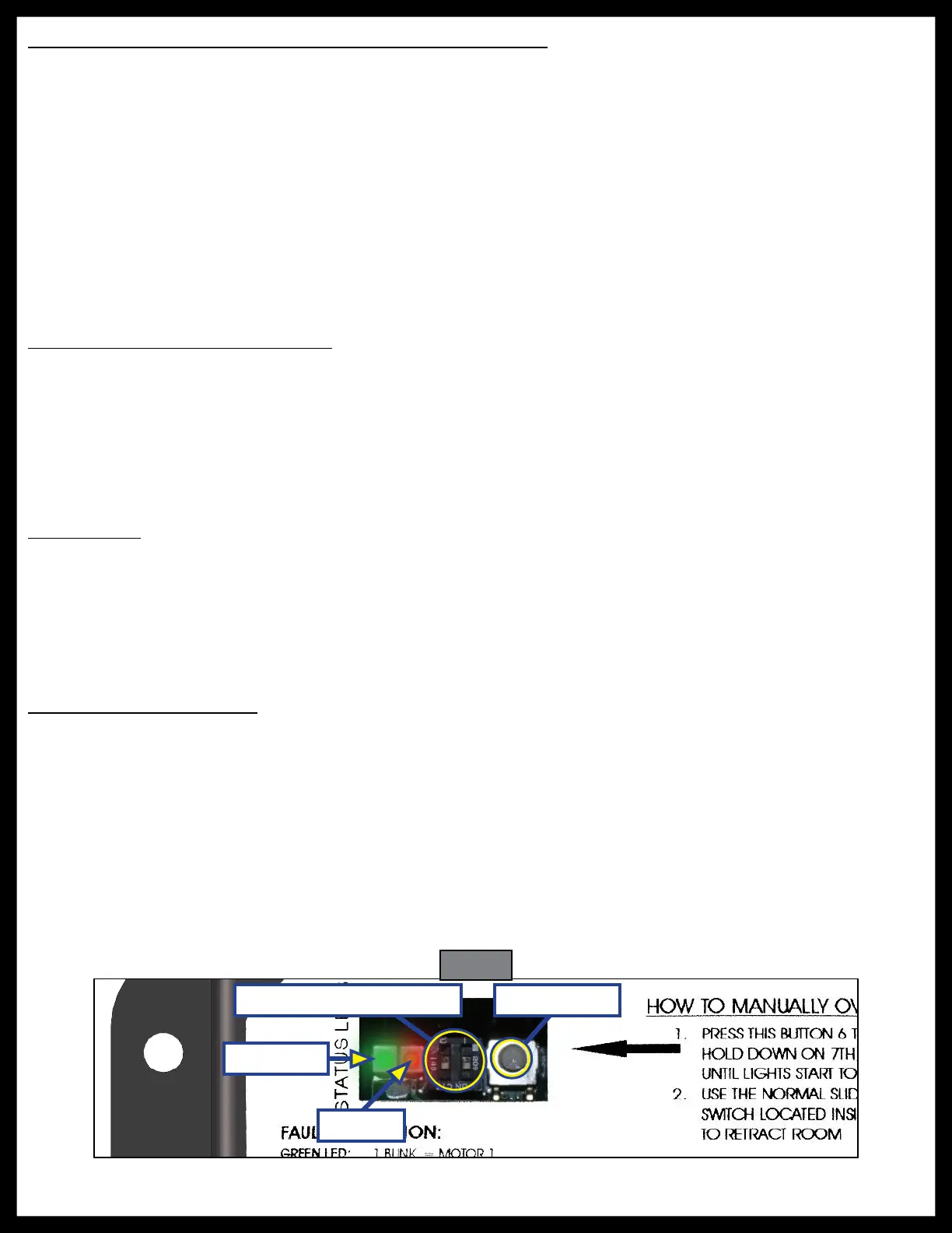
Fig. 24
Green LED
Red LED
Motor Direction Switches Mode Button
Electronic Manual Override (Controllers C-1 and C-2 Only)
NOTE: See (Fig. 24) for locations of the mode button and LEDs.
1. Press the mode button on the controller six times and hold on the seventh for five seconds to enter
electronic manual override mode.
2. Use the extend/retract switch to move both motors in or out.
NOTE: Over-current and short circuit detection are still enabled. Electronic manual override provides 12V
directly to both motors.
3. To exit the mode, push and hold the mode button until the LEDs begin to blink simultaneously. Exiting
the override mode resets the motor positions (you will have to resync motors).
NOTE: During this override procedure the motors are not synchronized. Visually watch the room: if one
side is moving significantly slower than the other (or not at all) then immediately stop and use the
"Motor Disengagement Procedure" below.
Motor Disengagement Procedure
1. Remove motor retention screws located near the top of each vertical column on the outside of the
coach (under bulb seal if equipped with bulb seal on column).
2. Locate motor.
A. On units built prior to 2011: Bend back wipe seal from outside of coach.
B. On units from 2011 to current: See slot in H-column on the inside of the coach.
3. Pull motor up until disengaged (roughly ½"). A flat-head screwdriver can be used to pry the motor up.
4. Reinstall motor retention screw to hold motor in place or remove motor.
Low Voltage
The Lippert IN-WALL® Slide-out Controller is capable of operating the room with as little as 8 volts. But at these
lower voltages the amperage requirement is greater. Check voltage at the controller, see Figs. 2 and 5 for the
location of power connections. If the battery is low, it needs to be charged or the unit should be plugged into shore
power or the generator can be run, if equipped. It may be possible to "jump" the RV's battery temporarily to extend
or retract the room. Consult the RV manufacturer's owners manual.
NOTE: Always connect directly to the battery and never to the controller power connections.
Motor Direction Switches
Motor direction switches (Fig. 24) are used to change the direction of individual motors. If when trying to extend
or retract the room, one side goes in and the other side goes out, then there is a problem in the wiring. The motor
direction switches can be used to correct this problem. The left switch controls motor 2 and the right switch
controls motor 1. If motor 1 is going in the wrong direction then change switch 1’s position. If motor 2 is going in
the wrong direction then change switch 2’s position.
The motor direction switches can also be used to change the direction of the extend/retract switch. If the room
extends when the extend/retract switch is moved to the retract position, its direction can be reversed by moving
both switch 1 and switch 2 to their opposite positions. This feature can be used if it is more convenient to change
the motor direction switches than to rewire the extend/retract switch.

 Loading...