5
lci1.com 574-537-8900 Rev: 10.23.19
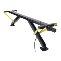
JT’s Strong Arm
™
Installation and Owner’s Manual
(For Aftermarket Applications)
CCD-0001455
3. At the front of the chassis, measure the inside distance
between the front electric leveling jacks just below the
frame of the chassis.
A. If measurement between front electric jacks is 58”
to 66” and the chassis is insulated and has a center
compartment with a steel oor located between the front
jacks, refer to step 4.
B. If measurement between the front jacks is 58” to 66”
and the chassis is uninsulated with a C-Channel cross-
member, refer to step 5.
C. If the measurement between the front jacks is 66” or
longer and the chassis is uninsulated with a C-Channel
cross-member, refer to step 6.
D. If the measurement between the front jacks is 66”
or longer and the chassis is insulated and has a center
compartment with a steel oor located between the front
jacks, refer to step 7.
E. If the measurement between the front jacks is 66” or
longer and the chassis is insulated and the cross-member
is constructed of tubular steel, refer to step 4.
F. If the measurement between the front jacks is less than
58”, use kit #191024.
4. Mark the bottom of the center compartment centered
between the front electric jacks. Mark the center of one of
the stiening pads between the mounting holes.
A. Align the center marks on the stiening pad and the
bottom of the center compartment and place the stiening
pad 1/4” from the front edge of the center compartment.
B. Mark the center of each mounting hole in the stiening
pad on the bottom of the center compartment and
centerpunch the marks.
C. To prevent accidental damage to personal property,
clear the center compartment of any valuables.
D. Drill a 1/8” pilot hole at each mounting hole location.
E. Drill 3/8” mounting holes. Use a countersink bit to
deburr the inside of the holes.
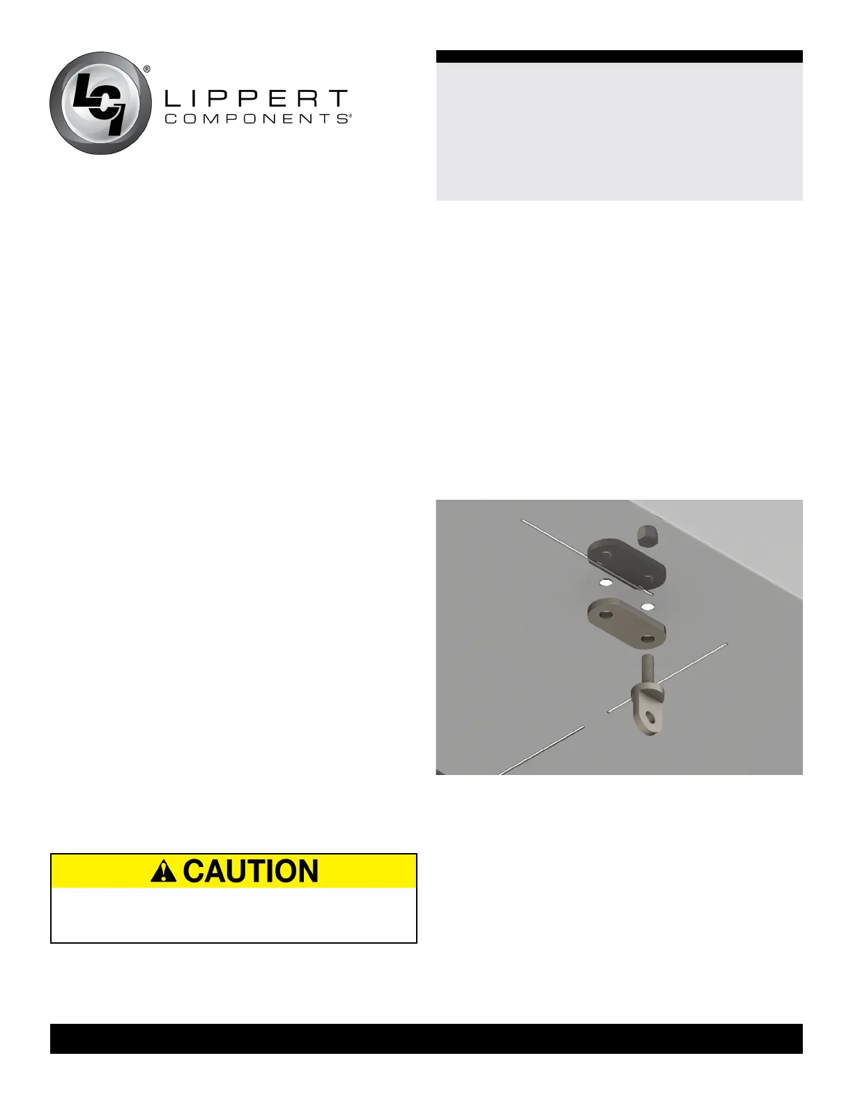
F. Sandwich the oor of the center compartment between
two stiening pads.
I. Insert two 3/8” - 16 x 1 1/4” swing bolts, two 3/8” SAE
at washers and two 3/8” - 16 Nyloc® nuts.
II. Tighten nuts enough to ensure needing a screwdriver
for leverage to pivot swing bolts (Fig.1).
Fig.1
REMOVE PERSONAL PROPERTY AND VALUABLES
FROM THE CENTER COMPARTMENT TO PREVENT
POSSIBLE DAMAGE OCCURING DURING DRILLING.
 Loading...