4
lci1.com 574-537-8900 Rev: 10.23.19
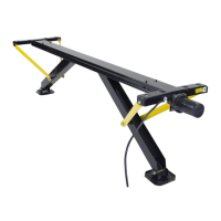
JT’s Strong Arm
™
Installation and Owner’s Manual
(For Aftermarket Applications)
CCD-0001455
Resources Required
• Tape measure
• Felt-tip black marker
• Hammer
• Center punch
• Electric or cordless drill or screw gun
• 1/8” drill bit (for pilot holes)
• 5/16” drill bit
• 3/8” drill bit
• 1/2” “Uni-bit,” or step bit, preferred—standard 1/2” drill
bit acceptable
• Countersink bit (for deburring)
• 9/16” deep socket and ratchet
• 9/16” box end wrench
• 5/8” box end wrench
• 11/16” box end wrench
• Locking pliers
• 3”-4” C-Clamp
• White grease
• Safety glasses
• Face shield
• Squeegee
Preparation
1. Make sure to park the trailer on solid, level ground.
2. Clear all jack landing locations of debris and
obstructions.
3. Locations should be free of depressions.
4. When parking trailer on extremely soft surfaces, utilize
load distribution pads under each jack.
5. People and pets should be clear of trailer while
operating leveling system.
Installation
1. For 2006 or later telescoping jacks:
A. Replace existing 3/8” jack pad bolt with 3/8” - 16 x 4”
swing bolt.
B. Use 3/8” - 16 nut to secure. Insert a 3/8” - 16 x 1 1/4”
swing bolt with the tab pointing to the rear of the chassis.
C. Secure with a 3/8” washer and 3/8” - 16 Nyloc® nut.
D. Prepare T-Bolts and stabilizer tubes as described in
step 12, except the inner tube should be set at 1” instead
of 5”.
E. After fully retracting rear telescoping jacks, attach the
clevis end of the stabilizer inner tube to the swing bolt tab
on the rear side of the jack using a 3/8” - 16 x 1 1/2” bolt
with a 3/8” washer on the top and bottom of the tab and a
3/8” - 16 Nyloc® nut.
F. Tighten nut until tight.
G. Repeat steps 1A-1F on opposite side.
2. Locate a cross-member rearward of the rear jacks at a
minimum of 6” to a maximum of 18”.
A. Under front half of chassis, locate a cross-member or
center compartment with a steel oor from 6”-18” from
front of electric leveling jacks.
NOTE: If unable to locate a suitable mounting location at
the front or rear of chassis, contact LCI customer service.
 Loading...