8
lci1.com 574-537-8900 Rev: 10.23.19
JT’s Strong Arm
™
Installation and Owner’s Manual
(For Aftermarket Applications)
CCD-0001455
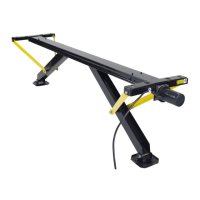
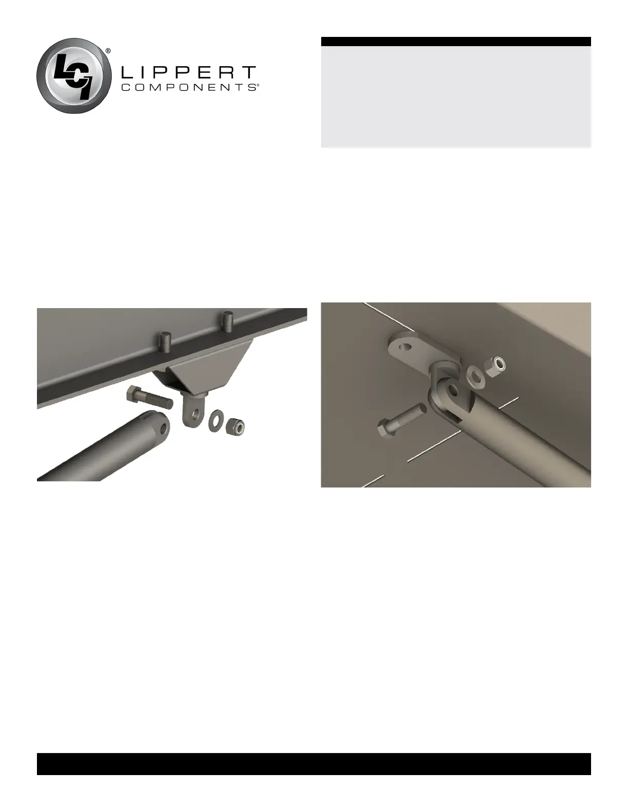
C. Secure a stiening pad to the bottom of the main rail
ange using a 3/8” - 16 x 1 1/4” swing bolt, a 3/8” washer
and a 3/8” - 16 Nyloc® nut.
NOTE: The edge of the stiening pad should be parallel to
the edge of the main rail ange.
D. Drill remaining mounting hole and secure with a
3/8” - 16 x 1 1/2” bolt, 3/8” washer and 3/8” - 16 Nyloc®
nut (Fig.4).
E. Repeat steps 10A-10D for opposite side of the chassis.
11. Measure from the rear side of the electric jack leg 27
3/4” and place a mark on the bottom of the main rails.
Assemble a spacer mount.
A. Using the spacer mount as a template, mark the
mounting holes by aligning one short edge with the
27 3/4” mark.
NOTE: The spacer mount should be parallel to the outside
of the main rail ange.
B. Center punch and drill 1/8” pilot holes at each mounting
hole location.
C. Re-drill the holes located closest to the front jacks to
5/16” on both sides of the chassis.
Fig.5
Fig.4
D. Tap the 5/16” holes with either a 3/8” - 16 tap or a 3/8” -
16 x 1” self-tapping bolt. Lubricate tap as needed.
E. Secure spacer mount to bottom of main rail ange
with a 3/8” - 16 x 1” self-tapping bolt, taking care to keep
the remaining pilot hole centered in the mounting of the
spacer mount. Tighten bolt securely.
F. Re-drill the remaining pilot hole to 5/16”. Then insert a
3/8” - 16 x 1” self-tapping bolt and tighten.
G. Repeat steps 11A-11F for opposite side of the chassis.
12. Apply white grease to the threads of two T-Bolts,
then partially thread them into the top holes of the outer
stabilizer tubes.
A. Remove inner stabilizer tube from assembly and
discard the plastic shipping bag.
 Loading...