Rev: 10.15.20 Page 5 CCD-0003688
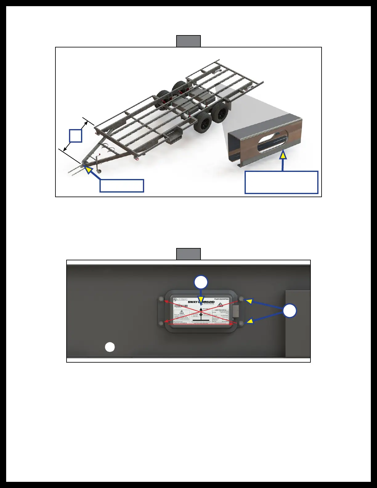
1. The controller (Fig. 1) must be mounted to a frame crossmember between 1219 mm - 3048 mm
(4ft-10 ft) behind the hitch point (Fig. 3A).
Fig. 3
Fig. 4
2. Prior to the floor being placed on the chassis, place the housing against the mounting surface. Use a
paint marker or grease pencil to locate the four mounting holes for the Sway Commandmodule (Fig. 4B).
3. Using a drill with the 5.5 mm drill bit, drill pilot holes through the crossmember at the four previously
markedlocations. Clear all chips from the mountingsurface.
A
4. After the holes have been drilled, insert M6 x 11.0 x 0.7 serrated external lock washers over each
#14 - 10 x 25 mm self-drilling hex screw.
5. Insert assembled screws into the module as follows:
A. Insert one screw into the module and tighten half way to hold the module in place.
B. Insert a second screw into the opposite corner from the previously installed screw and tighten half
way into the module to hold the module in place.
C. Insert a third screw into the open hole on the opposite end from the previously installed screw
and tighten half way into the module.
D. Insert the fourth screw into the remaining open hole and tighten half way into the module.
Hitch Point
Typical Structure of
Middle Rails
B
1
3
4
2
A