Rev: 10.15.20 Page 7 CCD-0003688
3. Connect the light pod to the OEM-provided electrical harness through the A-frame loom hole.
Note: The light pod wiring and connection point can be coiled into the cavity on the backside of the light
pod for a cleaner appearance, if preferred.
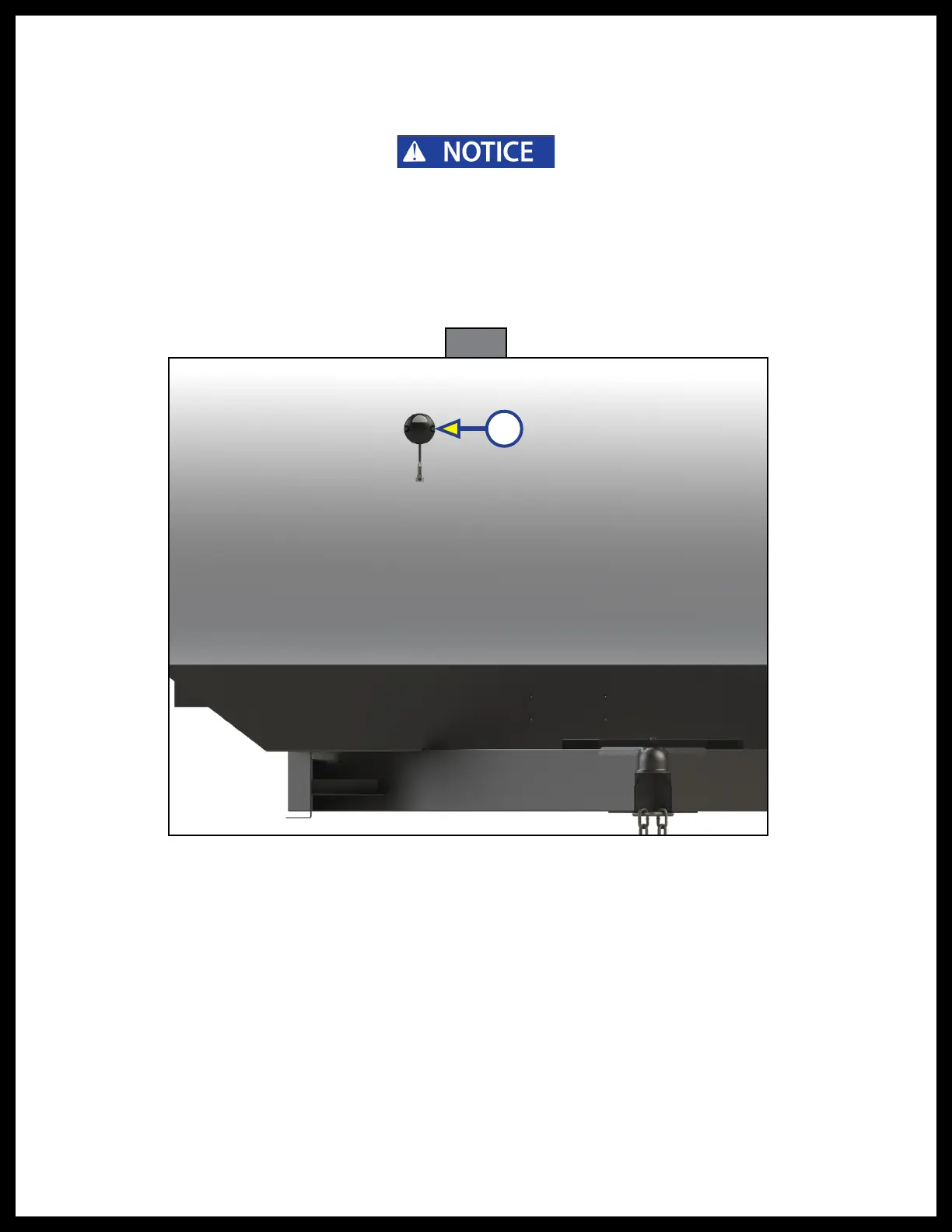
Mounting the light pod on a caravan wall:
1. Determine the proper mounting location for the light pod.
2. Attach the light pod (Fig. 6A) to the caravan wall with two M8 x 25 mm square head wood screws.
3. Connect the light pod to the OEM-provided main harness.
4. Make sure all wall penetrations are sealed to prevent water infiltration.
All electrical wiring harnesses shall be loomed and secured to prevent possible damage and
installed in accordance with best shop practices.
Fig. 6
Testing the System
During the end-of-line (EOL) test phase, the OEM-provided Vehicle Simulator Box will be connected to
thecaravan. Do as follows:
1. Turn the Auxiliary supply on—the LED will turn green if the system is operating correctly. The LED will
blink every five seconds. This is normal.
Note: Refer to the Light Code and Troubleshooting tables for additional information.
A