EasyManua.ls Logo

Lippert THEATER SEATING User Manual

Default Icon
4 pages
To Next Page IconTo Next Page
Page #1 background imageLoading...
Page #1 background image
Rev: 04.30.21 Page 1 CCD-0004339
THEATER SEATING
MECHANISM REPLACEMENT
TI-397
FURNITURE
Purpose
This document outlines the procedure for removing and replacing the theater seating mechanism.
Safety
Read and understand all instructions before installing or operating this product. Adhere to all safety labels.
The "CAUTION" symbol above is a sign that a procedure has a safety risk involved and may cause
personal injury, product and/or property damage if not performed safely and within the parameters
set forth in this document.
Use appropriate personal protective equipment (PPE) for the procedure being performed.
Moving parts can pinch, crush or cut. Keep clear and use caution.
Resources Required
Procedure
Removing the Seating Mechanism Base
1. Unplug the theater seat from its power source.
2. Place the theater seat on a clean soft surface.
3. Make sure the foot rest (Fig. 1A) is in the extended position.
4. Raise the back flap (Fig. 2A) of the theater seat to expose the backrest wires and latches.
1 to 2 people depending on task
Cordless or electric drill or screw gun
Appropriate drive bits
Drill bit extension
10mm Ratchet
Cutting tool
Zip ties
Fig. 2 Fig. 1
A
A
Question and Answer IconNeed help?

Do you have a question about the Lippert THEATER SEATING and is the answer not in the manual?

Lippert THEATER SEATING Specifications

General IconGeneral
BrandLippert
ModelTHEATER SEATING
CategoryAutomobile Accessories
LanguageEnglish

Summary

Purpose

Safety

General Safety Precautions

Read and understand all instructions, use appropriate PPE, and be aware of moving parts.

Resources Required

Procedure

Removing the Seating Mechanism Base

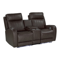
Steps to remove the theater seating mechanism base from the seat.

Disconnecting Power Wires and Seat Cushion

Disconnect power wires and remove the back cushion from the seat.

Removing Mechanism Base from Footrest Kick Plate

Remove bolts holding the mechanism base to the foot rest kick plate.

Removing LED Light Assembly

Cut zip ties and slide the LED light down and off the mechanism base.

Disconnecting Additional Wires and Base Mechanism

Disconnect LED, AC/DC, and motor wires, then remove screws holding the base mechanism.

Lifting and Setting Aside Base Mechanism

Lift the base mechanism up and set it aside after removing all fasteners.

Replacing the Seating Mechanism Base

Installing Foot Rest Stabilizer and New Base Mechanism

Install the foot rest stabilizer and align the new base mechanism with seat cushion screw holes.

Securing Mechanism Base and Reconnecting Wires

Install screws, connect motor, AC/DC, and LED wires, and secure the foot rest kick plate.

Finalizing Installation and Testing

Flip seat, install back rest, reconnect wires, and plug in to test functions.

Related product manuals