24 25
VALVES
VALVES WITH 110VAC SOLENOIDS
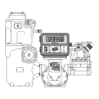
In order for the LectroCount LCR-II to control valves with
solenoids on 110 VAC circuits, you must install a relay
switch on the positive leg of the solenoid’s circuit.
Switch: SPST (single pole, single throw)
Switch Position: Normally open
Contact Rating: Greater than maximum current
of solenoid
Voltage: +12 VDC
Materials needed for wiring valves with 110 VAC
solenoids:
Not supplied with the valve
• SPST relay switch (1 per solenoid)
• 18 AWG stranded wire (2 per solenoid)
• Weatherproof exible conduit, ½" diameter and ½" NPT
conduit connectors or cable glands
• PTFE tape or pipe sealant
To wire 110 VAC solenoids to the LCR-II:
1. Turn off all 100 VAC circuits before beginning the
installation.
2. Install the specied relay switch(es) onto one leg of the
110 solenoid power supply circuit.
3. Connect the relay switch on the S1 power supply circuit
to terminals 15 and 16 on block J13.
4. Connect the relay switch on the S2 power supply circuit
to terminals 17 and 18 on block J13.
Turn off all 110VAC circuits before beginning
the installation.
Disconnect Power (110VAC)
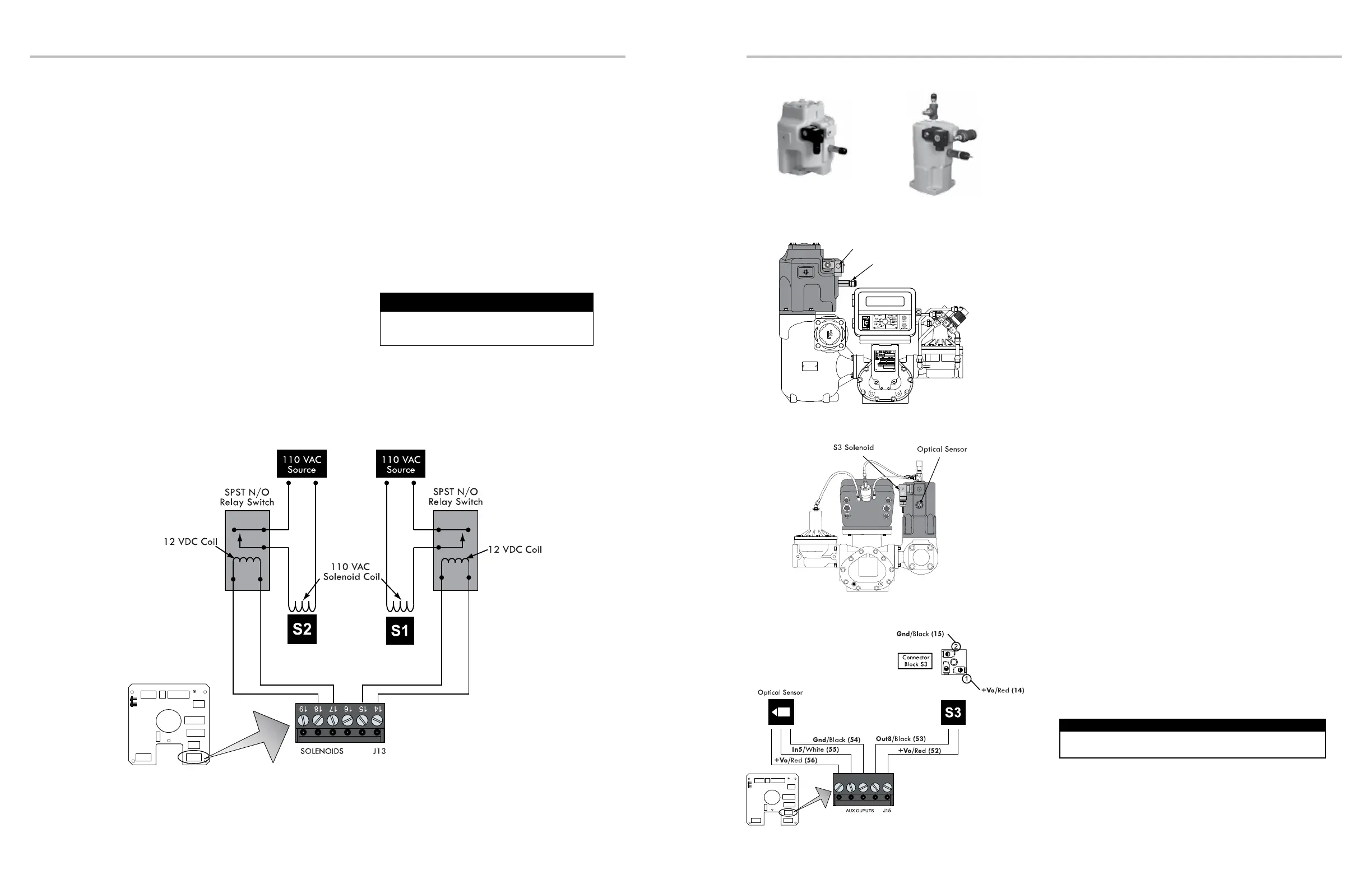
OPTICAL AIR & VAPOR ELIMINATORS
Optical Air Eliminator:
Rened Fuels
Optical Vapor Eliminator:
LPG and NH
3
S3 Solenoid
Optical Sensor
LectroCount LCR-II
Gallons
S3
52 53 54 55 56
Meter System with Optical Vapor Eliminator
Meter System with Optical Air Eliminator
Optical Air and Vapor Eliminator
Installations
When ordered as part of a meter system with a LCR-
II, Liquid Control’s optical air and vapor eliminators
are bolted onto the strainer and wired to the LCR-II
at the factory. Optical air and vapor eliminators can
also be ordered separately and installed onto meter
systems already in service. For mechanical installation
instructions, refer to the manual specic to the optical
air and vapor eliminator. Instructions for wiring optical air
and vapor eliminators to the LCR-II are provided on this
page.
Materials needed for wiring valves:
Not supplied
with the air or vapor eliminator
• 18 AWG stranded wire (2 for the S3 solenoid valve)
• Weatherproof exible conduit, ½" diameter and ½" NPT
conduit connectors or cable glands
• PTFE tape or pipe sealant
To wire optical air and vapor eliminators to the
LCR-II:
1. Attach cable glands and/or conduit connectors to the S3
solenoid valve, the optical sensor, and the LCR ports.
2. Thread the 18 AWG wires through a piece of
weatherproof conduit cut-to-length from the S3 solenoid
to a LCR-II port.
3. Run the weatherproof conduit between the S3 solenoid-
operated valve and the LCR-II housing. Pull the wires
through the ports, and tighten the connectors. Liquid
Controls recommends running the optical sensor wire
through weatherproof conduit as well.
4. Connect the three 18 AWG wires to the S3 solenoid-
operated valve terminals and to terminals 52 and 53 on
the J15 terminal block of the LCR-II CPU board.
5. Connect the optical sensor wires to terminals 54, 55, and
56 on the J15 terminal block of the LCR-II CPU board.
Disconnect the power before working on the CPU board.
Disconnect Power
 Loading...


