7
• insert joint end of upper link in-between yoke plates (4) (using upper or middle openings (3), and
then connect with pin and secure with linchpin (2);
• raise support (5) and secure with split pin;
• tighten chains limiting lateral deflections of tractor linkage,
• install chain (6) in upper transport hitch or its bracket (see section. 6.6. Mower adjustment rules).
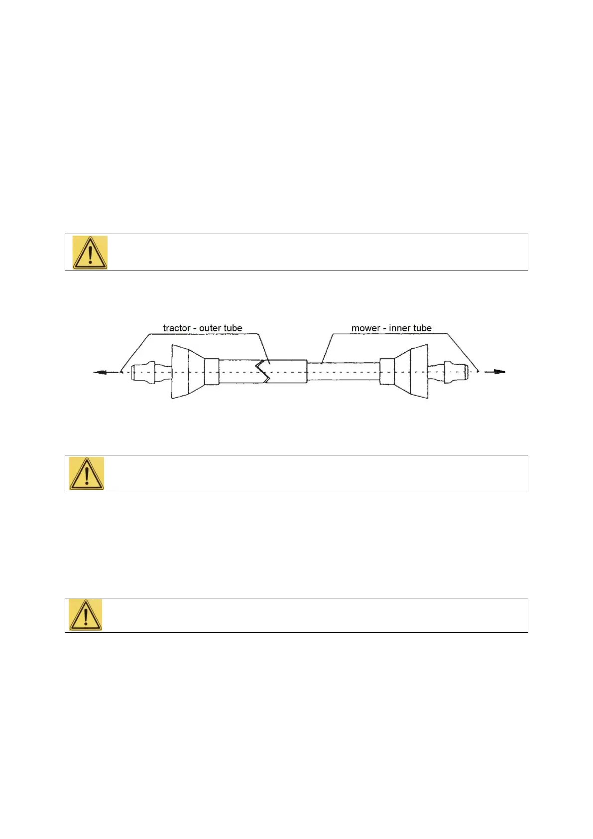
6.3. Installing U-joint shaft
For rotary mower drive, use U-joint shaft with “semi-concealed” cover, holding safety “B” mark
and characterised by technical parameters matching data in specification (refer to Table 2).
For use of the shaft with “semi-concealed” cover, additional covers from tractor PTO shaft and
machine power input connection side are required. Machine power input connection cover is installed
by manufacturer of the mower.
Use of U-joint shaft with parameters other than recommended by manufacturer of the
machine may cause its overloading and emergency damage or split of its both parts during
machine lifting and pose risk to service technicians and personnel around.
When installing U-joint shaft please remember that outer tube of shaft cover is positioned from
the tractor side (Fig. 4).
Fig. 4. U-joint shaft
It is forbidden to install (mount or remove) U-joint shaft with tractor engine running.
To install the shaft:
• lower the mower on the ground and turn off tractor engine and remove ignition key,
• slide shaft ends (yokes) over machine power input connection and tractor PTO shaft and secure
against slipping out using latches,
• check if latches effectively protect shaft ends against slipping out during operation,
• mount shaft cover chains; one to tractor PTO shaft cover, and the other to mower power input
connection cover.
It is forbidden to use U-joint shaft without cover or with damaged cover and without additional
covers from tractor PTO shaft and machine power input connection side.
 Loading...