34
l
LA-140 Quick Reference
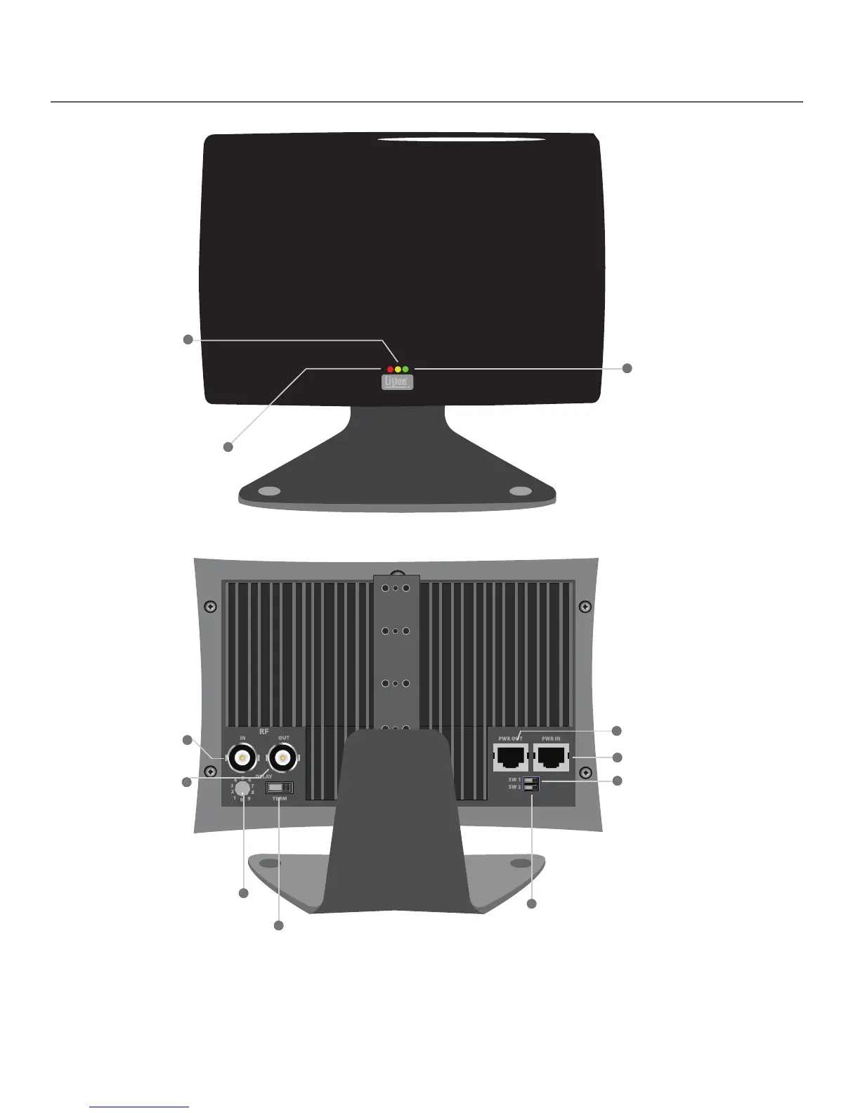
Power (Red):
This red LED is lit when
there is power to the radiator.
No Connection (Yellow):
This yellow LED indicates
a coaxial cable fault. If
illuminated, the radiator
is either not connected to
a powered transmitter or
another radiator.
RF Input:
Input RF signal from a
transmitter or radiator here.
RF Output:
Output RF signal to an
additional radiator here.
Power Input: Connect power here.
Carrier Present (Green):
This green LED is lit when
there is signal present to
the radiator. During normal
operation the red and green
LEDs will be continuously lit
(unless SW1 is o).
Delay Compensation Switch:
Adjust the amount of signal delay
from the radiator here. In single
radiator systems the position of
this switch does not matter, in
multiple radiator systems this
switch must be set properly.
See page 36.
Termination Switch: If there is no
RF being output from the RF
Output connection, this switch
must be in the “ON” position.
Default: ON
Power Output:
Output power to an
additional radiator here.
LED Indicator Shuto Switch (SW1):
Controls LED indicators on front of
radiator. If switch is set to the “OFF”
position, LEDs will not light up on
front of radiator. Default: ON
Listen Mode (SW2): If using a LA-140 Radia-
tor with another manufacturer’s transmit-
ter/modulator, it is necessary to put this
switch in the OFF position. IMPORTANT:
Always ensure SW2 is in the on position
when using a LT-82 transmitter. Default:
ON