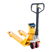
Thank you for using this hand pallet truck with scale. For your safety and correct operation of the scale, please
read these instructions carefully before using it.
NOTE: (1) All of the information reported herein is based on data available at the moment of printing. The
factory reserves the right to modify its own products at any moment without notice and incurring
any sanction. So it is suggested to always verify possible updates.
(2)
Prior to use this hand pallet truck with scale, the battery of scale must be charged enough.
Materials and specifications are subject to change without notice.
2. TOATTACHHANDLETO PUMPUNIT
2.1 Remove the handle component (H100), insert it into the pump shell (P06).
2.2 Remove the axle from plastic bag(P07)
2.3 Insert the axle (P07) at one end of the pump shell(P06), then pump shell (P06) and handle components
(H100) connection. Please note axle (P07) the position of the hole, Let the steel wire and nut on the chain
(H09) through the axle (P07) hole (See the hydraulic system diagram and the handle component diagram).
2.4 Spring pin (P08) fixed the axle(P07).
2.5 Handle (H01) press the pump plunger(P21), and remove the pin(P09).
2.6 Raise the crank link (P48) and put the pin on rod and chain (H09) into the groove of crank link (P48).
On the handle of the pallet truck, you will find the control lever (H01) which can be set in three positions
(See Fig. 1): LOWER=to lower the forks; NEUTRAL=to move the load; ASCENT=to raise the forks. After
assembling the handle, you can adjust the three positions.
3.1 First tighten the setting screw (P50) on the crank link (P48) until the LOWER position function works.
3.2 If the forks elevate while pumping in the NEUTRAL position, turn the setting screw (P50) clockwise until
pumping the handle does not raise the forks andthe NEUTRAL position functions correctly.
3.3 If the forks descend while pumping in the NEUTRAL position, turn the setting screw (P50)
counter-clockwise until the forks do not lower.
3.4 If the forks do not descend when the control lever (H01) is in the LOWER position, turn the setting screw
(P50) clockwise until raising the control lever (H01) lowers the forks. Then check the NEUTRAL position
as per item 4.2 and 4.3.
3.5 If the forks do not lift while pumping in the ASCENT position, turn the setting screw (P50) counter-
clockwise until the forks elevate while pumping in the ASCENT position. Then check the NEUTRAL and
LOWER position as per item 4.2, 4.3 and 4.4.
Please check the oil level every six months. Total oil amount is about 260 ml, add injection oil 50-100 ml,
this must be with the forks in the lowered position.
Add or change the hydraulic oil according to the table below.
 Loading...