Do you have a question about the Lochinvar Crest OFN0751 and is the answer not in the manual?
Indicates an imminently hazardous situation which, if not avoided, will result in death or serious injury.
Indicates a potentially hazardous situation which, if not avoided, could result in death or serious injury.
Indicates a potentially hazardous situation which, if not avoided, may result in minor or moderate injury.
Indicates special instructions on installation, operation, or maintenance that are important but not related to personal injury or property damage.
Provides instructions for installers and users regarding manual use, service, and safety compliance.
Highlights critical warnings about improper installation, fire/explosion hazards, and flammable vapor locations.
Details procedures for gas leaks and warnings regarding submerged appliances.
Outlines safety precautions for servicing and operating the boiler.
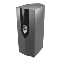
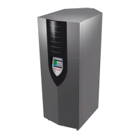
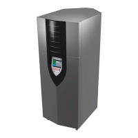
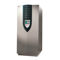
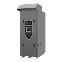
Describes key components like access panels, inlet hoods, drain connections, and condensate trap boxes.
Explains the electronic display, control module, gas valves, pressure switches, and relief valve.
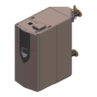
Details the firetube heat exchanger and water inlet/outlet connections.
Explains the venturi, air metering valve, and flame inspection window.
Lists model numbers, input/output MBH, and Net AHRI ratings.
Details boiler water content, water connection sizes, and gas connection sizes.
Notes on altitude derate and maximum working pressure.
Covers compliance with codes, outdoor installation requirements, and temperature/freezing warnings.
Details checks for connections, clearances, platform requirement, wind avoidance, and overhang clearance.
Addresses avoiding rain runoff, sprinklers, decks, recessed areas, and keeping the area clean.
DO NOT install units in areas that contain corrosive contaminants (see Table 1A).
Table 1A lists products and areas that may cause contaminated combustion air.
Specifies clearances from combustibles, for service, and foundation requirements.
Vent materials are field supplied; vent must terminate at least 36 inches above the unit.
Covers outdoor kit usage, specific vent caps, and installation warnings.
Ensures air purity and details clearances for wind, openings, and overhangs.
Details gas supply, regulator placement, filtering, and venting requirements.
Emphasizes proper piping support and safe gas leak detection methods.
Outlines precautions for pressure testing the gas supply and using pipe sealing compound.
Covers natural gas boiler setting, pipe sizing, and supply pressure requirements.
Covers propane gas boiler setting, pipe sizing, and supply pressure requirements.
DO NOT adjust or attempt to measure gas valve outlet pressure; could cause severe injury/damage.
Step-by-step guide to check inlet gas supply pressure using a manometer.
Warns against replacing the gas valve with a conventional type and cautions against adjusting its pressure.
Covers system cleaning, boiler water chemistry, and recommended additives.
Table 3A outlines recommended specifications for dissolved solids, pH, and chloride levels.
Do not use petroleum-based compounds or 'homemade cures'.
Details preventing dissolved oxygen and purging air from the water system.
Describes filling the system, testing water, and checking for gas leaks.
Covers checking thermostat circuits and inspecting the condensate system.
Includes final checks, starting the boiler, and troubleshooting common startup issues.
Focuses on checking system piping for leaks and venting remaining air.
Details checks for vent piping, gas piping, and flame/combustion analysis.
Steps to measure combustion using an analyzer via the flue collector.
Table 3B provides flue product ranges (CO2, O2) for different gas types and settings.
Procedure to test safety shutoff by manually closing the gas valve.
Emphasizes safety read-before-operating, gas smell checks, and leak procedures.
Step-by-step instructions for starting and operating the boiler.
Procedure for safely shutting off the gas supply to the appliance.
Schematic representation of electrical control logic for 751-2001 models.
Detailed electrical connections for 751-2001 models.
Schematic representation of electrical control logic for 2501-3501 models.
Detailed electrical connections for 2501-3501 models.
Schematic representation of electrical control logic for 4001-5001 models.
Detailed electrical connections for 4001-5001 models.
Schematic representation of electrical control logic for the 6001 model.
Detailed electrical connections for the 6001 model.