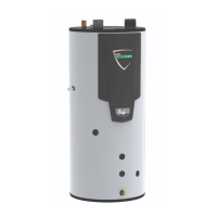
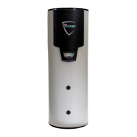
Do you have a question about the Lochinvar EcoShield SHW85-435CE and is the answer not in the manual?
Details on input, recovery rates, weights, gas types, and pressure requirements for EcoShield models.
Diagrams and itemized list for connecting the concentric flue system to specific models.
Step-by-step instructions for installing the concentric flue connection for specific EcoShield models.
Diagrams and itemized list for connecting the concentric flue system to larger EcoShield models.
Step-by-step instructions for installing the concentric flue connection for higher capacity EcoShield models.
Tables detailing combustion ventilation requirements for Type B appliances based on model and usage.
Guidelines for unvented systems, emphasizing the need for approved installers and compliance with regulations.
Detailed guidance on sizing and installing discharge pipework for relief valves, including safety considerations.
Table detailing normal supply voltage, fuse rating, and power consumption for each EcoShield model.
Detailed description of low voltage connection strip terminals for BMS, sensors, and control signals.
Schematic diagram illustrating the high voltage and low voltage wiring connections for the integrated control system.
Logic diagram illustrating the electrical control sequences and component interconnections.
Detailed breakdown of the unit's operational sequence and corresponding display messages during heating cycles.
Step-by-step guide for safely lighting the water heater after installation and checks.
Information on gas pressure adjustment, combustion figures, and CO2/CO readings for natural gas.
Essential pre-lighting checks for flueway, ventilation, system charge, gas supply, and condensate trap.
Procedure for commissioning and checking combustion for LPG-fired EcoShield units.
Table showing CO2 and CO figures for LPG combustion for different EcoShield models.
Procedure for converting the water heater from natural gas to LPG, including orifice plate insertion.
Detailed steps for converting SHW45-325CE to SHW85-435CE models to LPG fuel.
Detailed steps for converting the SHW145-435CE model to LPG fuel, focusing on orifice and manifold changes.
Detailed steps for converting the SHW115-435CE model to LPG fuel, including gas valve adjustments.
General advice on keeping the appliance area clear and performing annual checks on controls and safety features.
| Category | Water Heater |
|---|---|
| Brand | Lochinvar |
| Model | EcoShield SHW85-435CE |
| Capacity | 85 gallons |
| BTU Input | 435, 000 BTU/h |
| Fuel Type | Natural Gas |
| Input (BTU/h) | 435, 000 |
| Minimum Gas Supply Pressure (in. w.c.) | 5 |
| Maximum Gas Supply Pressure (in. w.c.) | 10 |


