

C
Christopher BrownAug 6, 2025
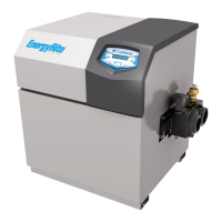
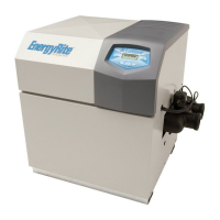
What to do if my Lochinvar EnergyRite ER202 Water Heater has no burner operation?
- Ddavid11Aug 6, 2025
If your Lochinvar Water Heater isn't burning, first, check the temperature setting on the main control board. Also, review the remote thermostat setting. If the pool heater is locked out due to a fault, check the display for the specific fault and refer to the fault descriptions for corrective actions.