11
•“COM”terminalsstandforCommon
In the corresponding terminal, connect the voltage supply for the corresponding load
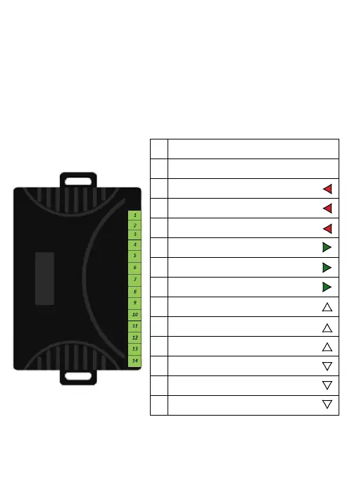
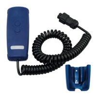
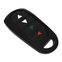
The table below with the matching gure shows the correspondence of the mini remote
control buttons with the corresponding outputs on the receiver.
1 DC 12V Positive power supply input (V+)
2 Negative power supply input (V-)
3 Channel D - Normal Closed of relay (NC)
4 Channel D - Common of relay (COM)
5 Channel D - Normal Open of relay (NO)
6 Channel C - Normal Closed of relay (NC)
7 Channel C - Common of relay (COM)
8 Channel C - Normal Open of relay (NO)
9 Channel A - Normal Closed of relay (NC)
10 Channel A - Common of relay (COM)
11 Channel A - Normal Open of relay (NO)
12 Channel B - Normal Closed of relay (NC)
13 Channel B - Common of relay (COM)
14 Channel B - Normal Open of relay (NO)


 To Next Page