Do you have a question about the Lombardini LDW 1204 and is the answer not in the manual?
General instructions for using the service manual.
Definitions of terms used in the manual.
Explanation of warning symbols and decals for safety.
Rules and regulations for safe engine operation.
Essential safety precautions during engine operation.
Measures to minimize environmental impact and ensure safety.
Guide to identifying and resolving engine problems and their symptoms.
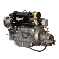
Information on identifying engine type, serial number, and specifications.
Detailed technical data and specifications for different engine models.
Graphical representation of engine performance curves (power, torque).
Dimensional drawings and measurements of various engine models.
Schedule and procedures for routine engine checks and maintenance.
Guidelines for selecting and using engine lubricants based on SAE and ACEA standards.
Information on coolant types, capacities, and safety precautions.
Requirements for diesel fuel quality and characteristics for optimal performance.
General guidelines and safety precautions before starting disassembly.
Best practices and safety advice for engine overhaul and tuning procedures.
Maintenance and identification of air intake components like filters and switches.
Instructions for removing and replacing the air filter support.
Steps for disassembling the intake manifold and remote air filter.
Components and general overview of the Exhaust Gas Recirculation system.
Detailed operation, disassembly, and reassembly of the EGR system.
Procedures for removing and installing the vacuum pump and its flange.
Steps for removing and replacing the exhaust manifold.
Safety precautions and procedure for cooling fan disassembly.
Instructions for checking and adjusting the alternator and cooling fan belt tension.
Safety and procedures for removing the optional fuel tank.
Safety and procedure for flywheel removal and ring gear replacement.
Procedures for removing and installing return and driving pulleys.
Mounting and assembly information for Ringfeder-type rings.
Steps for removing and refitting the timing belt cover.
Diagram and components of the timing belt and pulley system.
Procedure for removing and tightening the timing belt.
Notes on crankshaft timing pulley installation and reference marks.
Disassembly, assembly, and reference marks for the camshaft timing pulley.
Detailed procedure for reassembling the camshaft timing belt.
Using tools and procedures for camshaft timing belt tensioning.
Method for checking the engine's valve timing.
Timing angle specifications for intake and exhaust valves at different clearances.
List of components for the mechanical speed governor.
Procedure for governor spring removal, checks, and types for Gensets.
Details on the limiting speed governor used in automotive applications.
Procedure for reassembling the speed governor, with warnings.
Disassembly, reassembly, and clearance checks for the engine oil pump.
Description of the rocker arm cover's function and components.
Procedure for replacing the rocker arm cover gasket and torque settings.
Components and function of the crankcase vacuum relief valve.
Procedures for breather removal, fuel rail, and injection pump control rod.
Procedure for setting valve and rocker arm clearances when the engine is cold.
Non-return valve, disassembly, and rocker arm assembly procedures for the pump/injector unit.
Dismounting rocker arm pivots and camshaft disassembly and measurement.
Specifications for camshaft journals, housings, and lobe height.
Removing valves, sealing rings, and checking valve springs.
Specifications for valves, guides, housings, and insertion procedures.
Dimensions for valve seats and procedures for recess and sealing width checks.
Procedures for removing the pre-combustion chamber ring nut and chamber.
Instructions for installing the pre-combustion chamber, including torque specs.
Procedure for removing the engine oil pan, with safety warnings about used oil.
Procedures for dismounting and remounting stop pin rings.
Steps for piston disassembly, inspection, classification, and supply information.
Procedures for measuring piston weight, end gaps, and groove clearance.
Correct order for piston rings, measuring piston clearance, and assembly.
Step-by-step procedures for tightening cylinder head bolts for specific engine models.
Procedures for big end bearings and specifications for rods, bearings, and pins.
Checking rod alignment and measuring cylinder diameters and roughness.
Installing central, front, and rear bearing caps, and checking bearing-to-journal clearances.
Installing coolant nozzles, fitting shoulder half rings, and measuring crankshaft axial clearance.
Procedures for replacing crankshaft oil seal rings and information on oversized half rings.
Cleaning lubrication lines and checking crankshaft journals and crank.
Diameter specifications for crankshaft journals and connecting rod pins.
Diameter specifications and clearance values for main bearings and connecting rod ends.
Introduction to turbochargers, their components, and pressure testing procedures.
Procedure for adjusting the turbocharger waste gate.
Overview of the engine lubrication system and its components.
Internal oil filter, oil sump return pipe, and oil pump measurements.
Procedures for oil pressure regulating valve, filter cartridge, and pressure check.
Overview of the engine coolant circulation system and its components.
Procedures for checking the radiator, pump components, and thermostatic valve.
Overview of the fuel system, filter, lift pump, and drive rod projection.
Introduction to the pump/injector unit and its detailed components.
Procedures for plunger barrel ring nut, injection pump, and plunger reassembly.
Dimensions for pumping elements and control data for specific unit serial numbers.
Table of injection advance values for various pump/injector unit types and references.
Procedures for setting old-type injectors, current units, and checking nozzle projection.
Procedure for replacing the injector spark arrester and related components.
Detailed steps for controlling and regulating injection advance, including tables.
Tuning static advance, using timing belt protector references, and TDC identification.
Tools and procedure for injection advance control on old type pumps.
Procedure for regulating static injection advance using the delivery control rod.
Preliminary steps for pump/injector unit delivery balancing and test head assembly.
Connecting instruments and the procedure for balancing injection pump deliveries.
Description of the electric control panel and identification of its auxiliary terminals.
Specifications and performance curve for the Iskra 14V 33A alternator.
Wiring diagram for the 12V electric starting system with Iskra alternator and battery recommendations.
Specifications and performance curve for the Marelli AA 125 R 14V 45A alternator.
Wiring diagram for the 12V electric starting system with Marelli alternator.
Description and types of flywheel alternators.
Charging curves for 12V 20A and 30A flywheel alternators.
Wiring diagram for the 12V electric starting system with flywheel alternator.
Connection details for voltage regulators with different models.
Specifications and performance curve for the Bosch DW 12V 1.1 KW starter motor.
Specifications for the Bosch DW 12V 1.6 KW starter motor.
Performance curve for the Bosch DW 12V 1.6 KW starter motor.
Characteristics of the glow plug and its control unit with temperature sensor.
Characteristics of temperature sensors, oil pressure switch, and lamp sensors.
Procedures for setting engine idle speed and maximum speed.
Approximate adjustment of injection pump delivery without a dynamometer.
Function of the injection pump flow limiter and torque gearing device.
Procedure for setting the engine stop mechanism.
Procedure for timing the pump/injector unit with the speed governor.
Procedure for setting pump/injector delivery using a braked engine.
Table of required engine settings based on typical applications.
Guidelines for storing the engine when not installed.
Steps for applying protective measures for engine storage.
| Number of Cylinders | 4 |
|---|---|
| Fuel System | Indirect injection |
| Aspiration | Naturally aspirated |
| Starter | Electric |
| Engine Type | Diesel |
| Cooling System | Liquid |
| Power Output | 18.5 kW (25 hp) |