21
Inspection for camshaft
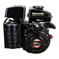
Check rising distance of each cam.
Measure length A in right picture by micrometer
Check abrasion
Items Standard date Limits
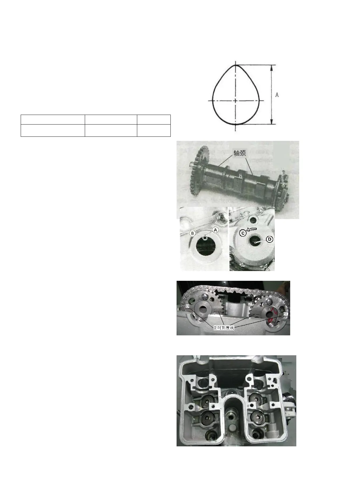
Check neck diameter of each camshaft
for confirming abrasion
Air intake and exhaust cam
Standard data:22.967~22.980
Limit data:22.94
Installation of camshaft
Aline timing marks
Turn crankshaft D anticlockwise and
aline timing mark A on left front cover and
mark B(T shaped scale line) on magnetor
through viewing C on left front cover, and
now the piston is at upper stopping point of
compression stroke.
Timing scale line “—” should be parallel with
joint surface of cylinder head when installing
camshaft.
(Note: Air intake cam corresponds scale line
of “IN” while air exhaust cam of “EX”)
Spread lubricant on neck of camshaft and cam.
Disassembly of cylinder head
Remove air intake tube
Remove joint of water pipe
Remove cylinder head cover
Remove bracket of camshaft
Remove camshaft
Remove bolt connects cylinder body
Finally remove cylinder head
 Loading...