Lonza • 1200 Lower River Road, P.O. Box 800 • Charleston, TN 37310-0800 • 1-800-4-PULSAR
3
rev.3 (3/12/14)
The Major Components - How They Work
General Principles of Operation
The three main components of the Pulsar
®
140
Chlorinator are (from top to bottom) the Briquette
Hopper, the manifold spray section and the
discharge tank. The water from the pool enters
the Pulsar
®
140 Chlorinator via the inlet port.
The spray manifold then distributes the water
onto the briquette grid creating a chlorinated
solution. The chlorinated solution falls into the
discharge tank and is discharged into the pool
recirculation system by the evacuation system.
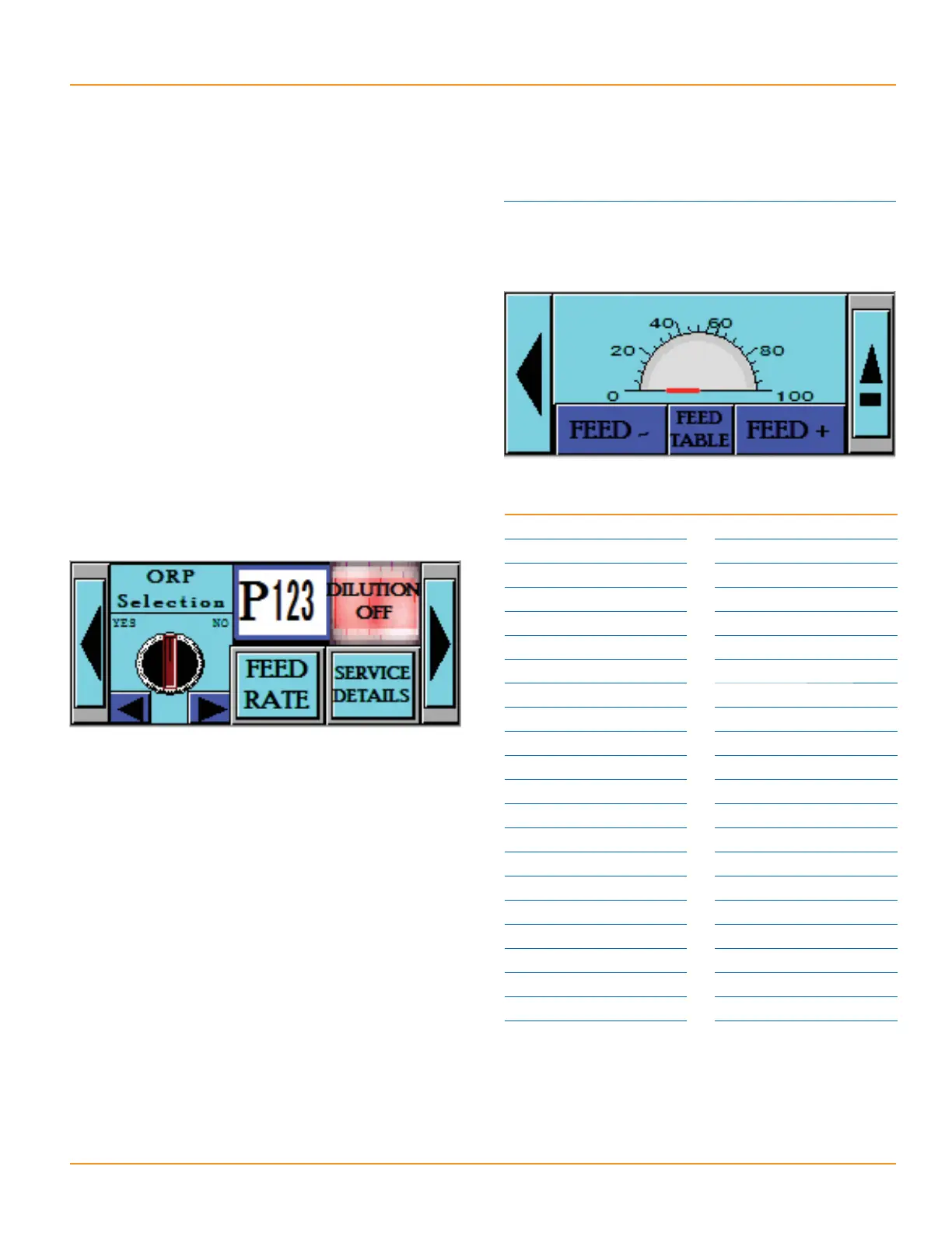
The amount of chlorine discharged from the
feeder is determined by the ORP controller or the
Timer. When using an ORP controller with this
unit, select “Yes” for the ORP or “No” to use
the internal Timer.
Inlet water pressure of 35 to 45 psi [2.41-3.10
bar] is required to provide sufficient flow into
the Pulsar
®
140. These pressures will result in
an inlet flow of 0.75 gallons/minute [2.84 lpm].
The Pulsar
®
140 feed rate settings referred to
in the Pulsar System Owners manual (right) are
calibrated for this flow rate.
Flow out of the Pulsar
®
140 discharge tank
requires a vacuum to drain. A minimum outlet
flow-rate of 2.5 gpm [9.46 lpm] ensures that the
flow out of the Pulsar
®
140 exceeds the flow in.
Once the Pulsar
®
140 is installed, outlet flow can
be measured by watching the level in the bottom
tank. If the level is rising as the feeder is running,
there is insufficient flow out.
Figures in Chart below represent Chlorinator
Output in Pounds of Available Chlorine per Day
Using the arrows on the touch screen, set the
timer to the desired “% output rate”
% output rate lbs [kg] Av. Cl
100 163 [73.9]
95 155 [70.2]
90 147 [66.5]
85 139 [62.8]
80 130 [59.1]
75 122 [55.5]
70 114 [51.8]
65 106 [48.1]
60 98 [44.4]
55 90 [40.7]
50 82 [37.0]
45 73 [33.3]
40 65 [29.6]
35 57 [25.9]
30 49 [22.2]
25 41 [18.5]
20 33 [14.8]
15 24 [11.1]
10 16 [7.4]
58[3.7]
00[0.0]
 Loading...