17
GB
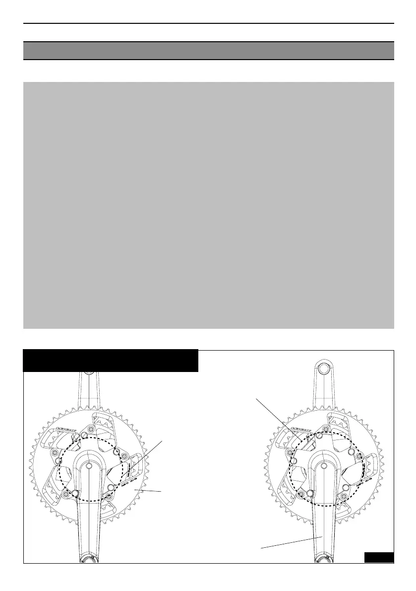
CHECKING THE FITTING
Fig 5
Chainring bolt holes spread out
over a 130mm-diameter circle
(the largest) for fitting double
chainrings.
Chainring bolt holes spread out
over a 110 mm-diameter circle
(the smallest) for fitting compact
chainrings.
The marking on the small
chainring should appear through
the large chainring.
The 2 markings should be
juxtaposed. This is the best
configuration for gear change.
Direction of the chainrings by
alignment of the chain securing
device behind the right-hand
crank.
Checking fitting of the chainrings:
When fitting the chainrings, check the following:
- The direction of the chainrings so that gears can be changed correctly for standard chainrings.
- That 130mm bolt patterns are placed on the outermost of the spider and 110mm bolt patterns are
placed on the innermost holes as shown in Figure 5.
- That the LOOK engravings are in the direction shown on figure 5 for LOOK specific chainrings.
- The position of the chain securing device on the outer chainring to prevent the chain from be-
coming stuck between the chainring and the crank. This chain securing device should be located
behind the crank.
- Torque of chain wheel attachment screws: 6 Nm.
IMPORTANT:
LOOK recommends use of its specific chainrings designed for the ZED 2 crank assembly for the fol-
lowing reasons:
- The specific shapes of the teeth of each LOOK chainring to facilitate gear change have been devel-
oped especially for fitting on the double and/or compact ZED 2 spider.
- The resistance and rigidity of LOOK chainrings have been optimised by providing a larger contact
surface at the attachment of each spoke.
Important: the following flange combinations are not recommended:
- 42 x 51 teeth
- 44 x 51 teeth