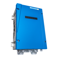
Controller Installation 4342 Controller Installation
EN EN7.4.2.1 General
When the controller operates in hybrid mode,
it is combining solar power and AC power. For
that reason both power sources are galvanically
connected together, which means always both
power sources must be safely disconnected during
installation or maintenance.
To be able to use both power sources in hybrid
mode, the PV voltage (real Vmp) must be higher
than the AC input voltage after it has internally been
rectied to DC.
AC input voltage min. real Vmp from PV
generator
380 V AC 535 V DC
400 V AC 565 V DC
460 V AC 650 V DC
480 V AC 680 V DC
For installing a hybrid system, ensure the steps in
„7.4.1 Controller wiring for solar only“ on page 29
have been completed before proceeding.
7.4.2.2 Electrical installation
It is the installers' duty to correctly install the AC
components like cable, AC disconnect/breaker and
AC fuses. The installation must comply with local
installation requirements and conditions.
Depending on the installation parameters and size
of system it might not be possible to install an RCD
or RCM as normal leakage currents could lead to
tripping in normal operation. If the use of an RCD is
required the installer needs to take care to install a
custom solution according to local standards.
7.4.2 .3 Input current and harmonics
Due to its rectier operation the AC input of the PSk3
draws a non-sinusoidal current (harmonic currents)
from the supply source. This slightly increases
the maximum current value compared to pure
sinusoidal currents.
The absolute value of the current depends on
grid impedance and grid voltage. Technical data
calculation in „4.2 Technical Data of the PSk3
Controller“ on page 12 was calculated based on
a 400 V three-phase grid with a relatively low grid
impedance (strong grid).
If you connect the PSk3 to an oversized generator or
a strong grid it can draw a maximum RMS current of
up to 30 A per phase (see „4.2 Technical Data of the
PSk3 Controller“ on page 12) when supplying a 11
kW motor at full power.
All components of the installation have to be sized
according to this maximum current value.
If you are connected to a public grid where there
are requirements concerning maximum Harmonic
Distortions, you might need to install lters at
the AC input of the PSk3 to fulll local standards
requirements. Installing lters also reduces the RMS
current, which the PSk3 controller draws from the AC
source. More information about line and load lter
can be found on partnerNET.
7.4.2 Controller wiring for hybrid operation
l
WARNING – Do not dismantle the
controller while still connected to the
power supply! Before any installation,
maintenance or inspection activities wait
at least FIVE MINUTES after the power
supply has been disconnected from the
controller!
a
NOTE – PSk3 can be supplied by
solar and / or an AC source. This can
lead to an interaction of both sources,
especially if the system is not properly
installed. Special care must be taken
when installing the PSk3 controller in
hybrid conguration. Carefully read the
following chapters.
a
CAUTION – This product can cause
current with a DC component. Where
a residual current-operated protective
(RCD) or monitoring (RCM) device is used
for protection in case of direct or indirect
contact, only an RCD or RCM of Type
B is allowed on the supply side of this
product.
The PSk3 controller is supplied with a special small
1.5 Wp PV module (pre-wired for crimping). This PV
module is used to measure the solar irradiation and
allows you to set irradiation dependent START / STOP
values for the pump. These settings can only be
done via LORENTZ Assistant. (Please check LORENTZ
partnerNET and the LORENTZ Assistant manual).
l
WARNING – Do NOT use any other PV
module than the one supplied or the PSk3
controller may be damaged.
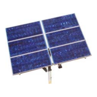
Mount the PV module with the same alignment as
the solar array that powers the pump system. For
example, if the solar array is tilted at an angle of
20°, the PV panel for the Sun Sensor should be tiled
exactly the same. You can ensure this by mounting
the PV module on the frame of the PV module array.
Take care of correct polarity.
l
WARNING – Voltage reversal of the
Sun Switch panel will lead to damage of
the controller.
WARNING – You must not exceed
the maximum voltage or current ratings
for any part of the system.
Please see "9 Pump Accessories Installation" on
page 71 for more information on the available
accessories and refer to the product manuals on
partnerNET.