Operating the Pump 8786 Pump Accessories Installation
EN EN
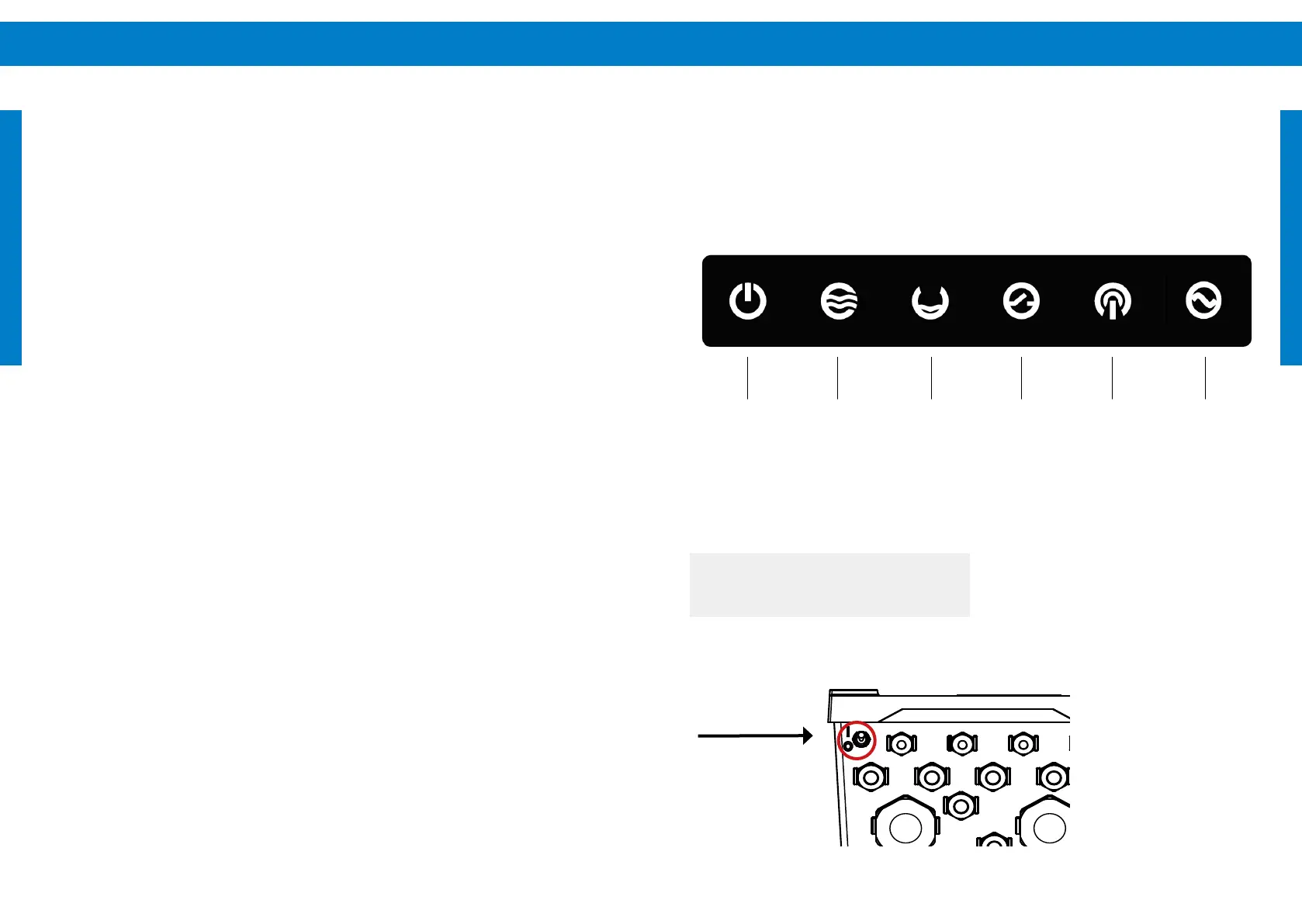
ON/OFF switch
Local
communication
AC status
POWER SWITCH (ON/OFF)
l
WARNING – The switch only switches
pump operation ON/OFF. It is not a
disconnect switch.
When switched OFF/ON during operation, it resets
the system.
10 Operating the Pump
This graphic displays the front LED indicators of the
PSk3 controller. For a detailed description of the LED
status indication please refer to "10.1 LED Status" on
page 88.
The on/o switch is located at the bottom of the
controller.
9.12 .7 LED status
A ashing red LED indicates that the battery voltage
is low.
A permanent green LED indicates that the power
of the PSk3 is on and that the PSk3 controller is
charging the SmartStart.
A ashing green LED indicates that the SmartStart
supplies the PSk3 controller with power.
A permanent yellow LED indicates that the
generator relay is switched on.
Wiring
The wiring must be done by qualied sta only. In
the kit there is a green 2-pin plug with two pre-
assembled cables (black and red). The 2-pin plug
must be removed from the board before wiring. The
corresponding socket on the right upper edge of the
board is labeled with the correct cable conguration.
("Figure 56: Opened SmartStart" on page 85)
Battery
Use the 2-pin plug ("Figure 56: Opened SmartStart"
on page 85) with the pre-assembled cables. The
red cable is for plus (+), the black cable is for minus
(-).
Make sure the cables are securely mounted to the
battery. Ensure and check the correct polarity.
Remove the battery xing. Slide in the battery.
Ensure the battery is correctly seated and secure it
with the battery xing.
Remote switchSource lowPump statusSystem status