Do you have a question about the LOVATO ELECTRIC RGK900 and is the answer not in the manual?
| Model | RGK900 |
|---|---|
| Manufacturer | LOVATO ELECTRIC |
| Frequency | 50/60 Hz |
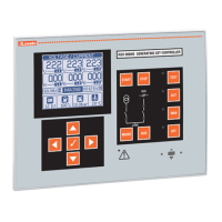
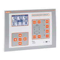
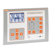
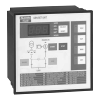
| Mounting | Panel mounting |
| Operating temperature | -20 to +70 °C |
| Relative Humidity | 95% non-condensing |
| Certifications | CE, UL |
| Type | Generator Control Unit |
| Storage temperature | -30 to +80 °C |
General safety precautions for installation and use, handling of live parts, manufacturer responsibility, and cleaning instructions.
General warning for installation and use, handling of live parts, manufacturer responsibility, and cleaning instructions.
Details applications for RGK900 (AMF, baseload, peak shaving) and RGK900SA (island, AMF with RGK900MC).
Explains PID control loops for synchronization and load sharing, affecting engine speed (governor) and voltage (AVR).
Guides on experimentally adjusting PID parameters for governor and AVR, accessible while the engine is running.
How to manually control engine speed and observe PID effects.
How to manually control AVR output and modulate generator voltage.
How to adjust PID parameters for stable reference frequency, including parameters P33.09-P33.12.
How to set the phase PID (P33.13) for phase shift control, using synchroscope and bar graph.
How to adjust voltage control parameters (P34.09-P34.12) for matching nominal or source voltage.
How to adjust active power PID parameters (P33.14-P33.16) for load sharing and power ramps.
Enables defining up to 16 programmable alarms, including source, message text, and properties.
Allows setting ladder programs using Customization manager for internal PLC logic and variable management.
Explains the periodic automatic test, its scheduling, and how to enable/disable it via setup or front panel.
Details connecting RGK900 to ECU, reading measurements, simplifying wiring, and diagnostics.
Details on modifying parameter values, using navigation keys, and the auto-save/exit functionality.
Settings for interlock time, feedback alarm delay, switchgear type, and opening commands.
Parameters for MIN/MAX voltage limits, delays, asymmetry, frequency limits, and mains control modes.
Parameters for max current, short-circuit, ground fault, thermal protection, and automatic test settings.
Settings for enabling automatic test, interval, start time, duration, and load switching during tests.
Settings for input functions, index, contact type, and delays for up to 32 digital inputs.
Settings for ECU type, operating mode, ECU power input, and alarm redirection from CAN.
Parameters for start-up on power threshold, load shedding, dummy load management, and overload alarms.
Defines reference measurement, source, channel, function (Max/Min/Min+Max), thresholds, delays, and state for limit thresholds.
Settings for application type (GEN-GEN, GEN-RETE), voltage, frequency, phase differences, synchronization, power ramps, and reverse power alarms.
Parameters for governor control type, polarity, output levels, PWM frequency, band alarm, and PID coefficients for frequency, phase, and active power.
Parameters for AVR control type, polarity, output levels, PWM frequency, band alarm, and PID coefficients for voltage and reactive power.