I038 I GB 07 06
1
INDICE GENERALE ................................................................. Pag. 1
GENERALITÀ .......................................................................... 2
Descrizione del frontale .......................................................... 2
MODO DI FUNZIONAMENTO .................................................. 2
Funzionamento OFF................................................................ 2
Funzionamento MANUALE ..................................................... 2
Funzionamento AUTOMATICO ............................................... 3
Funzionamento TEST ............................................................. 3
DESCRIZIONE DEL FUNZIONAMENTO .................................. 3
Ciclo di avviamento gruppo elettrogeno ................................ 3
Ciclo di arresto gruppo elettrogeno ....................................... 3
Segnale motore avviato ......................................................... 4
Presenza tensione rete ........................................................... 4
Presenza tensione generatore ................................................ 4
Commutazione Rete/Gener. e Gener./Rete ............................. 5
Intervento allarmi .................................................................. 5
Visualizzazione delle misure .................................................. 5
FUNZIONI .............................................................................. 6
Test automatico ..................................................................... 6
Abilitazione e disabilitazione test aut. .................................... 6
Arresto di emergenza ............................................................. 6
Avviamento a distanza ........................................................... 6
Telecommutazione ................................................................. 6
Funzionamento per motopompa ............................................ 7
Contaore funz. gruppo elettrogeno ........................................ 7
Intervallo di manutenzione ..................................................... 7
Allarme cumulativo ................................................................ 7
Controllo remoto ................................................................... 7
INFORMAZIONI, ALLARMI E ERRORI ................................... 8
Informazioni .......................................................................... 8
Tabella messaggi ................................................................... 8
Allarmi ................................................................................... 8
Tabella allarmi ....................................................................... 10
Errori ..................................................................................... 10
Tabella errori ......................................................................... 10
INGRESSI E USCITE .............................................................. 11
Tabella ingressi ...................................................................... 11
Tabella uscite ......................................................................... 11
PROGRAMMAZIONE ............................................................. 12
PARAMETRI .......................................................................... 12
Tabella setup base ................................................................. 12
Tabella setup esteso .............................................................. 13
Tabella setup allarmi utente ................................................... 15
CARATTERISTICHE TECNICHE .............................................. 16
NORMATIVE DI RIFERIMENTO .............................................. 18
SCHEMI DI COLLEGAMENTO ............................................... 19
CONNESSIONI MORSETTIERA RGAM ................................... 20
DIMENSIONI .......................................................................... 20
CONTENTS ............................................................................ Page 1
DESCRIPTION ....................................................................... 2
Front plate .............................................................................. 2
OPERATING MODE DESCRIPTION ........................................ 2
OFF Mode .............................................................................. 2
MANUAL Mode ...................................................................... 2
AUTOMATIC Mode ................................................................. 3
TEST Mode ............................................................................ 3
OPERATING DESCRIPTION ................................................... 3
Start-up cycle of generating set ............................................. 3
Stop cycle of generating set .................................................. 3
Engine started signal ............................................................. 4
Mains voltage present ........................................................... 4
Generator voltage present ..................................................... 4
Mains/Gen and Gen/Mains changeover ................................. 5
Alarm tripping ........................................................................ 5
Readings display ................................................................... 5
FUNCTIONS ........................................................................... 6
Automatic test ....................................................................... 6
Enabling and disenabling automatic test ............................... 6
Emergency stop ..................................................................... 6
Remote starting ..................................................................... 6
Remote changeover ............................................................... 6
Close coupled pump operation .............................................. 7
Operating hour counter of generating set ............................. 7
Maintenance .......................................................................... 7
Common alarm ...................................................................... 7
Remote control ...................................................................... 7
INFORMATION - ALARMS- ERRORS ..................................... 8
Information ............................................................................ 8
Messages table ...................................................................... 8
Alarms ................................................................................... 8
Alarms table .......................................................................... 10
Errors .................................................................................... 10
Errors table ............................................................................ 10
INPUTS AND OUTPUTS ......................................................... 11
Inputs table ............................................................................ 11
Outputs table ......................................................................... 11
PROGRAMMING .................................................................... 12
PARAMETERS ....................................................................... 12
Basic setup table ................................................................... 12
Advanced setup table ............................................................. 13
User’s alarms setup table ...................................................... 15
TECHNICAL CHARACTERISTICS ........................................... 16
REFERENCE STANDARDS ..................................................... 18
WIRING DIAGRAMS .............................................................. 19
RGAM TERMINAL BLOCK CONNECTIONS ............................ 20
DIMENSIONS ......................................................................... 20
1
ATTENZIONE!!
Questo apparecchio deve essere installato da personale qualificato,
nel rispetto delle vigenti normative impiantistiche, allo scopo di
evitare danni a persone o cose.
I prodotti descritti in questo documento sono suscettibili in qualsiasi
momento di evoluzioni o di modifiche. Le descrizioni ed i dati nella
documentazione non possono pertanto avere alcun valore contrattuale.
WARNING!!
This equipment must be installed by trained personnel, complying to
current standards, to avoid damages or safety hazards. Products
illustrated herein are subject to alterations and changes without prior
notice. Technical data and descriptions in the documentation are
accurate to the best of our knowledge, but no liabilities for errors,
omissions or contingencies arising therefrom are accepted.
LOVATO ELECTRIC S.P.A.
24020 GORLE (BERGAMO) ITALIA
VIA DON E. MAZZA, 12
TEL. 035 4282111
TELEFAX (Nazionale): 035 4282200
TELEFAX (International): +39 035 4282400
E-mail info@
LovatoElectric.com
Web www.
LovatoElectric.com
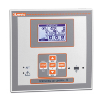
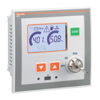
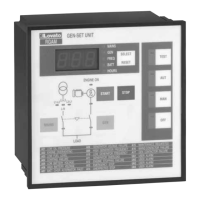
RGAM
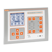
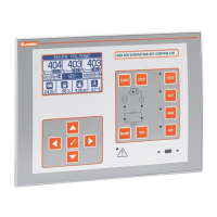
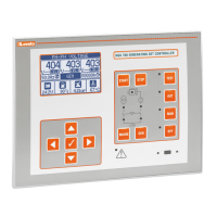
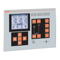
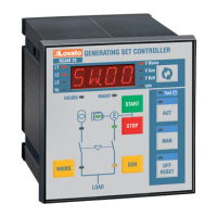
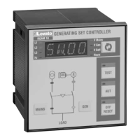
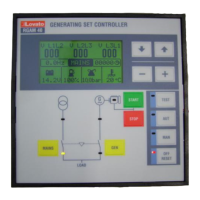
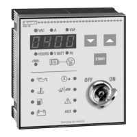
I UNITÀ DI CONTROLLO PER GRUPPI ELETTROGENI
GB CONTROL UNIT FOR GENERATING SETS