Doc: MHIT102B0206.doc 01/06/2007 p. 1 / 23
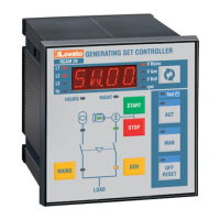
RGAM40 RGAM40
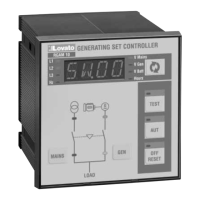
RGAM41 RGAM41
RGAM42 RGAM42
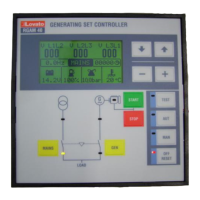
Unità di controllo per gruppi Gen-set controller
elettrogeni con commutazione with AMF function
automatica Rete-Generatore (Automatic Mains Failure)
MANUALE OPERATIVO INSTRUCTIONS MANUAL
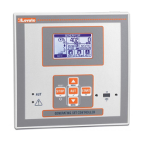
Introduzione
Questo apparecchio è stato progettato per unire la massima semplicità di
utilizzo con una ampia scelta di funzioni avanzate. Il display grafico LCD
consente una avanzata interfaccia utente, e la dotazione di ingressi/uscite
permette all’ RGAM4x una vasta gamma di applicazioni.
Introduction
This device has been designed to integrate the maximum operation
easiness with a wide selection of functions. The graphic LCD display
allows an advanced user interface, and the input-outputs endowment
makes the RGAM4x suitable for a wide range of gen-set applications.
Descrizione
• Controllo del gruppo elettrogeno con gestione automatica della
commutazione rete-generatore (AMF)
• Ingresso di misura rete trifase
• Ingresso di misura generatore trifase
• Alimentazione universale 12-24Vdc
• LCD grafico 128x64 retroilluminato per visualizzazione misure
• Testi in 5 lingue: Inglese-Italiano-Francese-Portoghese-Spagnolo
• 9 LED per visualizzazione modalità di funzionamento e stati
• Tastiera a membrana 12 tasti.
• Interfaccia di comunicazione RS232 per set-up, controllo remoto e
supervisione.
• 3 Ingressi analogici per sensori resistivi
• 8 ingressi digitali programmabili
• 7 uscite a relè , tutte programmabili
• Ingresso pick-up e W per rilevamento velocità motore
• Interfaccia di comunicazione RS485 per controllo remoto (versione
RGAM41)
• Interfaccia di comunicazione CANbus per controllo ECU motore
(versione RGAM42)
• Orologio datario con riserva di energia (versione RGAM41 e RGAM42)
Description
• Gen-set control with automatic management of the AMF (Automatic
Mains Failure) function
• Three-phase mains measurement input
• Three-phase generator measurement input
• 12-24Vdc universal power supply unit
• Graphic LCD display, 128x64 pixels, backlighted
• Texts in 5 languages: English-Italian-French-Porttuguese-Spanish
• 9 LEDs for status and operating mode indication
• 12-key membrane keyboard
• RS232 communication interface for set-up, remote control and
supervision
• 3 analog inputs for resistive sensors
• 8 programmable digital inputs
• 7 relay outputs, all programmable
• Engine speed input for W or magnetic pick-up signals
• RS485 communication interface for remote control and supervision
• (RGAM41 version)
• CANbus communication interface for engine ECU control
(RGAM42 version)
• Real time clock with back-up capacitors (RGAM41 and RGAM42
versions)
ATTENZIONE!! Questi apparecchi devono essere
installati da personale qualificato, nel rispetto delle vigenti
normative impiantistiche, allo scopo di evitare danni a persone
o cose.
I prodotti descritti in questo documento sono suscettibili in
qualsiasi momento di evoluzioni o di modifiche.
Le descrizioni ed i dati a catalogo non possono pertanto avere
alcun valore contrattuale
WARNING! This equipment is to be installed by qualified
personnel, complying to current standards, to avoid damages or
safety hazards. Products illustrated herein are subject to alteration
and changes without prior notice. Technical data and descriptions
in the documentation are accurate, to the best of our knowledge,
but no liabilities for errors, omissions or contingencies arising
therefrom are accepted.