Do you have a question about the LOVATO ELECTRIC RGK601 and is the answer not in the manual?
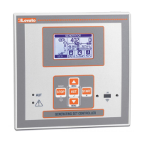
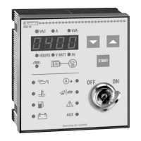
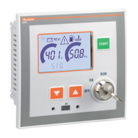
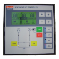
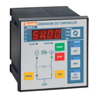
Details the available versions and key features of the RGK600 series controllers.
Explains the function of each button on the controller's front panel.
Describes the meaning of the front panel LED indicators.
Details how to change the controller's operating mode (STOP, START, AUT).
Instructions on how to supply power to the RGK600 series controllers.
Describes the initial state upon power-up and essential parameter settings.
Describes the main menu structure and icon navigation.
Explains how to enable and use password protection for access.
Details the information shown on the main home page.
Explains the various measurement screens available.
Details the screens for displaying energy meter readings.
Displays engine speed, fuel level, and tank capacity information.
Shows fuel autonomy calculations and generator thermal protection status.
Displays engine hours, work counters, and maintenance interval status.
Shows the list of logged events with date, time, and code.
Provides system information such as software version and serial number.
Explains configuration for resistive sensors (fuel, oil, temperature).
Details remote start functionality for SA models via specific inputs.
Describes inputs, outputs, internal variables (LIMx, REMx), and counters.
Explains how to set limit thresholds for measurements and their functions.
Details the operation of Max, Min, and Max+Min threshold functions.
Describes variables that can be modified remotely.
Explains how to define and configure user-specific alarms.
Details the functionality and configuration of the automatic test feature.
Explains how to put the controller into a low power sleep mode.
Describes connecting the controller to engine ECUs via CAN bus.
Explains how diagnostic messages are displayed.
Details diagnostic trouble codes (DTC) from engine ECUs.
Describes using the IR port for device configuration and service.
Explains using PC software for transferring and setting parameters.
Details how to access and navigate the setup menu using front panel keys.
Covers utility, general, password, battery, alarms, engine, and sensor settings.
Includes load changeover, voltage control, protection, and automatic test.
Covers maintenance, inputs, outputs, communication, and remote alarms.
Includes user alarms and miscellaneous settings.
Describes the interface for modifying parameter values.
Lists and explains parameters in the Utility menu (M01).
Details general system specifications and CT/VT parameters.
Details password protection and access level parameters.
Details parameters for selecting and managing multiple configurations.
Configures battery voltage settings and related alarms.
Configures siren and buzzer behavior for various alarm conditions.
Sets engine speed reading source, limits, and alarm delays.
Configures oil pressure sensor input and alarm settings.
Configures coolant temperature sensor input and alarm settings.
Configures fuel level sensor input and alarm settings.
Sets engine start thresholds, delays, and preheating parameters.
Configures delays and sequences for engine start attempts.
Defines operating modes for fuel valve, choke, and stop magnet outputs.
Configures switchgear type, delays, and load transfer logic.
Sets limits, delays, and hysteresis for mains voltage monitoring.
Sets limits, delays, and hysteresis for generator voltage.
Configures frequency limits and delays for generator operation.
Configures generator current, short-circuit, and thermal protection.
Configures automatic test schedule, duration, and behavior.
Sets service intervals and defines how maintenance time is counted.
Configures functions, index, and type for digital inputs.
Configures functions, index, and state for digital outputs.
Sets ECU type, operating mode, and power for CAN bus communication.
Configures dummy load and load shedding for managing generator load.
Configures EJP modes, remote alarms, and other special functions.
Sets measurement thresholds, multipliers, and delays for alarms.
Further details on EJP, remote alarms, and input/output control.
Sets up event counters, their source, and description.
Configures remote output functions for signals and alarms.
Defines user-defined alarms, alarm sources, and custom messages.
Details parameters for configuring user alarms (source, channel, text).
Explains how alarms are displayed, indicated by LEDs, and managed.
Describes available properties for alarms like enabled, retained, and siren.
A comprehensive table listing all alarms and their properties.
Lists alarms related to generator performance, system faults, and contactors.
Lists alarms for fuel tank status, battery issues, and CAN bus communication.
Lists alarms for fuel filter, configuration, water in fuel, and user-defined alarms.
Describes alarms related to engine temperature, oil pressure, and fuel level sensors.
Describes alarms for battery status, starting failures, and engine stops.
Describes alarms for generator frequency, voltage, current, and phase sequence.
Describes alarms for system errors, contactor faults, and battery charger issues.
Describes alarms related to CAN bus communication and ECU errors.
Explains how to assign functions to digital inputs.
Details specific functions like remote stop, start, and test activation.
Lists available functions for programmable outputs (e.g., starter, fuel valve).
Details functions for outputs like ECU power, alarms, and remote variables.
Explains how to execute commands for maintenance, reset, and configuration.
Details command functions and required user access levels for execution.
Provides instructions for installing the device into a panel for flush mounting.
Instructions for fixing the unit with clips and screws, and for disassembly.
Advice on making electrical connections referencing diagrams and specifications.
Shows wiring connections for three-phase sets with W signal input.
Shows wiring connections for three-phase sets with Pick-up signal input.
Illustrates CAN bus wiring, termination resistors, and connections.
Shows how analog inputs can be wired and used as digital inputs.
Wiring diagram for single-phase generating sets.
Wiring diagram for two-phase generating sets.
Wiring diagram for sets with permanent magnet battery charger alternators.
Shows terminal assignments for RGK600/601/600SA/601SA models.
Shows terminal assignments for the RGK610 model.
Provides physical dimensions and panel cut-out details for mounting.
Details power supply, current consumption, and digital input parameters.
Details specifications for analog inputs and speed signal (W/Pick-up).
Details specifications for mains and generator voltage and frequency.
Details current input and SSR output characteristics.
Specifies operating environment, connections, and certifications.
Lists changes made to the manual across different revisions.
| Frequency | 50/60Hz |
|---|---|
| Number of Switching Operations per Day | 16 |
| Time Base | Quartz |
| Protection degree | IP20 |
| Accuracy | ±1 second per day |





 Loading...