Док: I406RUGB09_15.docx 21/09/2015 p. 1 / 57
A
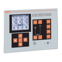
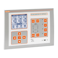
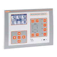
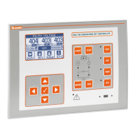
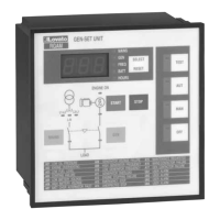
RGK900MC RGK900MC
Контроллеры Generating set
электрогенераторных установок control unit
РУКОВОДСТВО ПО
ЭКСПЛУАТАЦИИ INSTRUCTIONS MANUAL
● Перед тем как выполнять какие-либо работы на приборе, отключите напряжение с
клемм питания и измерения и замкните накоротко между собой клеммы трансформаторов
тока.
● Изготовитель не несет ответственность за обеспечение электробезопасности в случае
ненадлежащего использования прибора.
● Изделия, описанные в настоящем документе, в любой момент могут подвергнуться
изменениям
или усовершенствованиям. Поэтому описания и каталожные данные не могут
считаться действительными для целей контрактов.
● Выключатель или размыкатель должен входить в состав системы электроснабжения
здания. Он должен находиться вблизи прибора, и к нему должен быть обеспечен
свободный доступ пользователя. Он должен быть промаркирован как разъединяющее
устройство прибора: IEC/ EN 61010-1 § 6.12.2.1..
● Используйте для
чистки прибора мягкую тряпку; не применяйте абразивные средства,
жидкие моющие средства или растворители.
● Before any maintenance operation on the device, remove all the voltages from measuring
and supply inputs and short-circuit the CT input terminals.
● Products illustrated herein are subject to alteration and changes without prior notice.
● Technical data and descriptions in the documentation are accurate, to the best of our
knowledge, but no liabilities for errors, omissions or contingencies arising there from are
accepted.
● A circuit breaker must be included in the electrical installation of the building. It must be
installed close by the equipment and within easy reach of the operator.
It must be marked as the disconnecting device of the equipment:
IEC /EN 61010-1 § 6.12.2.1.
● Clean the instrument with a soft dry cloth; do not use abrasives, liquid detergents or
solvents
.
Оглавление Стр.
Введение 2
Описание 2
Функции клавиш прибора 3
Светодиоды на передней панели 3
Режимы работы 4
Подача напряжения на прибор 4
Главное меню 5
Доступ с использованием пароля 5
Навигация между страницами дисплея 6
Таблица страниц дисплея 6
Страница анализа гармони
10
Страницы формы волны напряжения 10
Страница пользователя 10
Модели и области применения 11
Примеры использования 11
Настройки для PID-регуляторов 12
Возможность расширения 13
Дополнительные ресурсы 14
Каналы связи 14
Входы, выходы, внутренние переменные, счетчики, аналоговые
входы
14
Пороговые значения (LIMx) 15
Дистанционно управляемые переменные (REMx) 16
варийные сигналы, программируемые пользователем (UAx) 16
Логика ПЛК (PLCx) 17
втоматическое тестирование 17
Модем GSM-GPRS 18
льтернативные конфигурации 19
ИК порт программирования 20
Настройка параметров через П
20
Настройка параметров с помощью клавиш на передней панели 21
Таблица параметров 24
варийные сигналы 41
Свойства аварийных сигналов 42
Таблица аварийных сигналов 43
Описание аварийных сигналов 44
Таблица функций входов 46
Таблица функций выходов 48
Меню команд 49
Монтаж 50
Схемы соединения 51
Расположение клемм 53
Механические размеры (мм) 54
Размеры отверстия для установки (мм) 54
Технические характеристики 55
История изменений руководства 57
Index Page
Introduction 2
Description 2
Keyboard functions 3
Front LEDs 3
Operating modes 4
Power-up 4
Main menu 5
Password access 5
Display page navigation 6
Table of display pages 6
Harmonic analysis page 10
Waveform pages 10
User pages 10
Models and applications 11
pplications examples 11
PID loops adjustment 12
Expandability 13
dditional resources 14
Communication channels 14
Inputs, outputs, internal variables, counters, analog inputs 14
Limit thresholds (LIMx) 15
Remote-controlled variables (REMx) 16
User alarms (UAx) 16
PLC Logic (PLCx) 17
utomatic test 17
GSM-GPRS modem 18
Multiple configurations 19
IR programming port 20
Parameter setting through PC 20
Setting of parameters (setup) from front panel 21
Parameter table 24
larms 41
larm properties 42
larm table 43
larm description 44
Input function table 46
Output function table 48
Commands menu 49
Installation 50
Wiring diagrams 51
Terminals arrangement 53
Mechanical dimensions (mm) 54
Panel cutout 54
Technical characteristics 55
Manual revision history 57
I406 RU GB 0915
ВНИМАНИЕ!!!
● Перед тем как приступать к установке и использованию прибора,
внимательно прочитайте настоящее руководство.
● Установка данных приборов должна производиться
квалифицированным персоналом в соответствии с действующими
нормативами во избежание несчастных случаев и аварий.
WARNING!
Carefully read the manual before the installation or use.
This equipment is to be installed by qualified personnel, complying to
current standards, to avoid damages or safety hazards.
RU