12
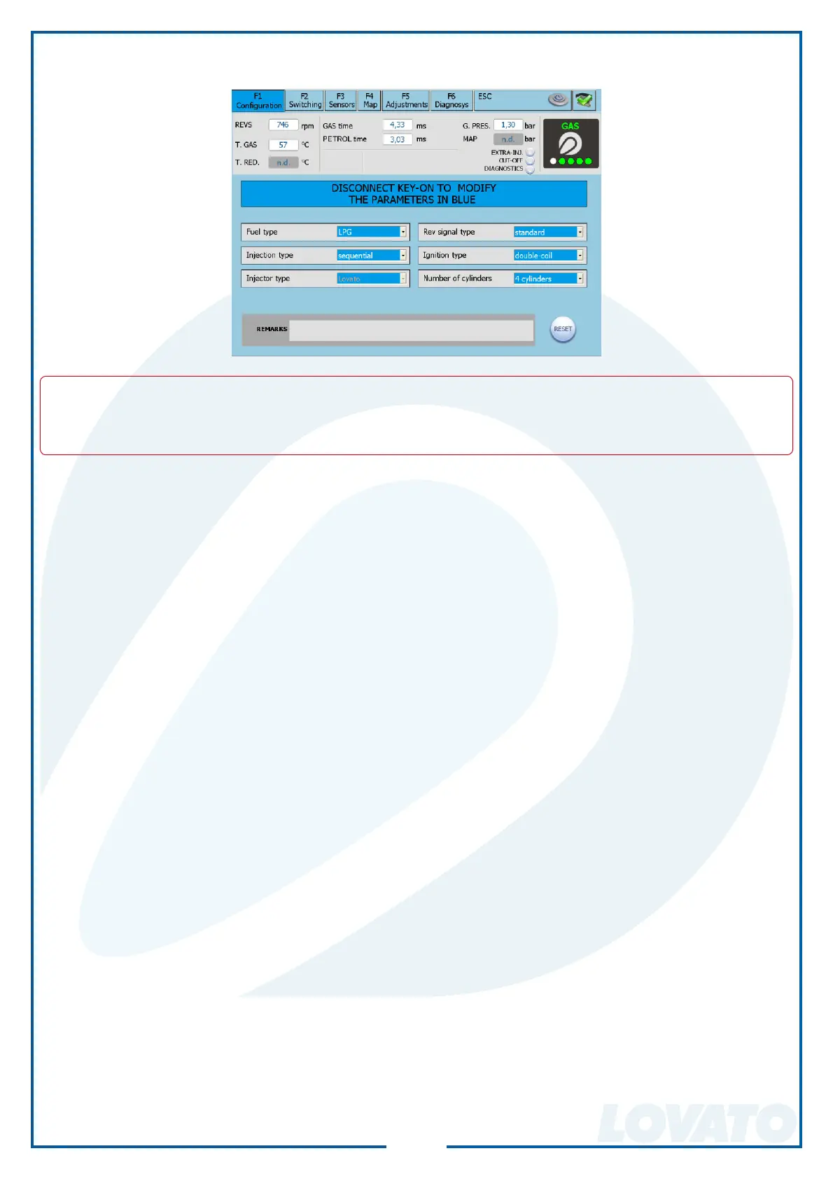
8.5.1 CONFIGURATION.
In this window it is possible to set the parameters that characterize the car.
WARNING
ALL PARAMETERS HIGHLIGHTED IN BLUE HAVE TO BE MODIFIED WITH DISABLED PANEL
AND OFF SWITCH.
• TYPE OF FUEL
This selection is used to initialize the control unit with the characteristic parameters previously set
for the correct operation with the type of fuel used. Select:
LPG for cars with LPG feeding.
METHANE for cars with METHANE feeding.
By selecting LPG or METHANE, moreover, it changes also the folder where the confi guration fi les
are saved (see Load confi guration).
• INJECTION TYPE
This function allows selecting the enabling strategy of the gas injectors with reference to the type
of system:
SEQUENTIAL (SUGGESTED OPTION) The GAS injector is enabled at each PETROL injection.
FULL GROUP The GAS injector is enabled every 2 PETROL injections.
• INJECTORS TYPE
This window allows selecting the type of GAS injectors supplied with the Installation kit.
Should a previously saved confi guration be loaded, this window shows the type of gas injectors
foreseen in the confi guration fi le.
If the type of gas injectors previously saved in control unit does not correspond to the ones shown
in this window, a warning message is displayed. To solve the problem, it is necessary to load a
confi guration fi le, which foresees the installed injectors, or to change the type of gas injectors
set in the control unit. Should the injectors installed on the car not match the selected ones, the
injectors are piloted by wrong parameters causing gas malfunctions or the damaging of the same
injectors.
• TYPE OF REVOLUTION SIGNAL
It pre-arranges the control unit for the detection of the revolution signal by means of the BLACK
wire:
STANDARD Select this option when the BLACK wire is connected to one of these signals:
- revolution counter wire with square wave signal 0 ÷ 12 V;
- coil negative.
WEAK SIGNAL Select this option when the BLACK wire is connected to one of these signals:
- revolution counter wire with square wave signal 0 ÷ 5 V;
- static switching-on signal with square wave signal 0 ÷ 5 V.
These signals can be identifi ed only using an oscilloscope.