Maintenance Instruction
5.6 Adjustment of traveling and steering system
5.6.1 Precaution for full hydraulic steering system
LOVOL series 4-wheel drivetractor adopts full-
hydraulic steering, as shown in figure.Before delivery, the steering
system is already adjusted.Please take note the following items during operation.
Frequently check the each threaded connection and tighten it if necessary.When full-
system is working, there should be no leakage at each connection.
During operation, if steering is heavy or fa
ilure, please firstly find out the cause. Do not forcefully rotate the
steering wheel. Never dismantle steering gear to avoid damage of parts.Never rotate the steering wheel by
two persons.
When installing full-hydraulic steering system, steering gear and steering shaft should be at the same axial
line with clearance at axial direction.After installation, check the steering wheel for flexible rotating.
Keep the oil clean.Therefore frequently check the filter element and oil level.Inspection method: drop an oil
droplet on the blotter. If there is a black center on the blotter, change the oil.
After changing oil, please vacuum the cylinder.Air bleeding method: loosen the steering cylinder bolt to
bleed air with oil pump at low speed until there is no bubble emerged in oil.Disconnect the link between the
steering cylinder piston rod and steering wheel. Rotate the steering wheel to let the piston at the leftmost or
rightmost (do not stay at the both extreme positions).
A flow dividing valve is of sophisticated pa
rts and not allowed to be dismantled without permission. If
removing it, please use clean gasoline or kerosene at clean site.
Before delivery, the flow dividing valve is already adjusted. Do not remove and adjust it by yourself.
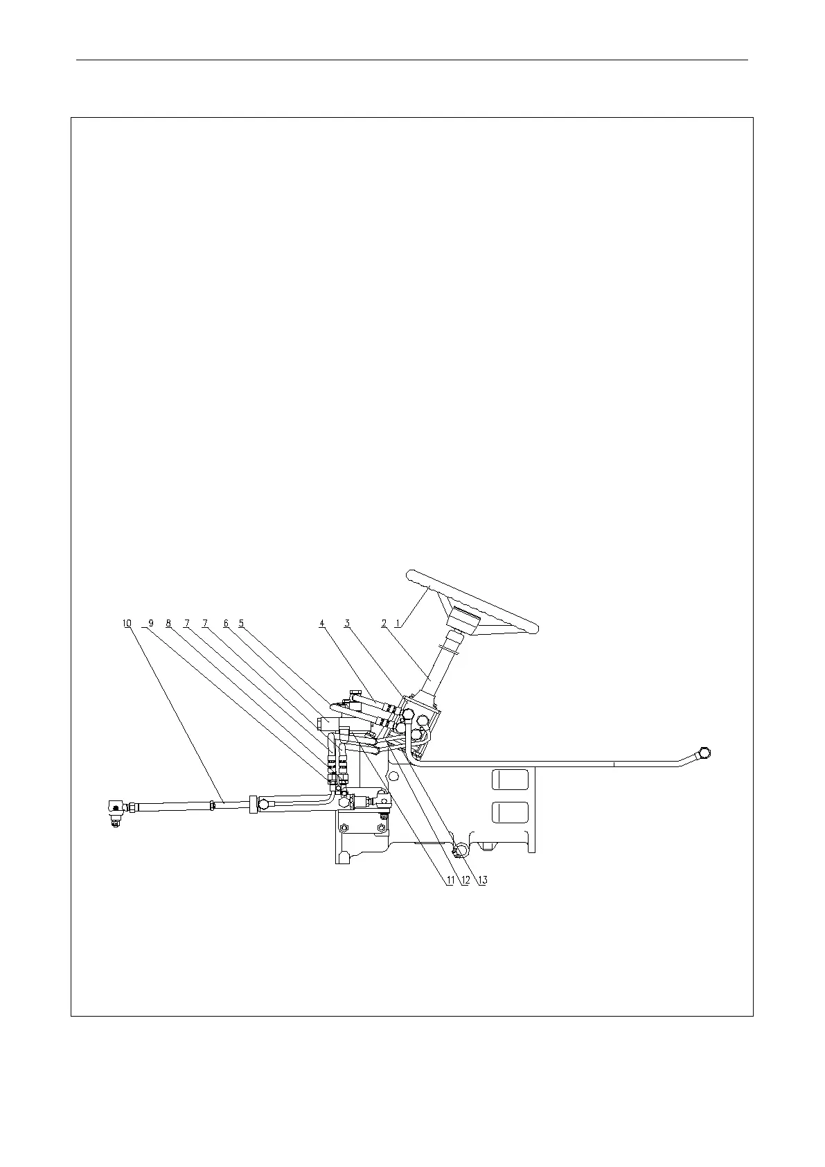
Fig.5-7 Full hydraulic steering system
1. Steering wheel assembly; 2. Steering column assembly; 3. Hydraulic steering gear; 4. Diverter valve oil return line; 5. Oil inlet
pipe of steering gear; 6. Stable splite-flow valve of single line; 7. Oil cylinder hose assembly; 8. Left tra
nsition pipe of cylinder; 9.
Right transition pipe of cylinder; 10 Drag link and steering cylinder assembly; 11. Welded bracket of splite-flow valve; 12. Right pipe
of cylinder; 13. Left pipe of cylinder
61