Do you have a question about the Lowrance Link-8 VHF and is the answer not in the manual?
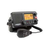
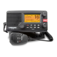
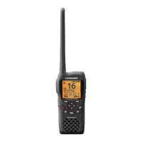
Overview of the Lowrance Link-8 marine band VHF radio's capabilities.
Instructions on personalizing radio settings and preferences.
Guide to navigating the radio's menu system and interface.
Method for inputting text and characters using the radio's controls.
Explanation of icons and symbols displayed on the radio's LCD screen.
Details on audible alerts and tone sequences for various radio events.
Instructions for creating, editing, and managing saved GPS waypoints.
Adjusting the screen and keypad brightness for optimal viewing.
Managing a list of contacts for quick calling and tracking.
Adjusting receiver sensitivity for noisy or quiet environments.
Adjusting the LCD screen contrast for readability.
Configuring and displaying GPS position, time, and navigation data.
Enabling a simulator for testing GPS functionality.
Restoring radio settings to their original factory configuration.
Selecting the appropriate VHF channel bank for your region.
Customizing channel name tags for easier identification.
Adjusting the volume for incoming DSC call alerts.
Setting the volume for button press confirmation beeps.
Choosing measurement units for distance and navigation.
Enabling or disabling the radio's internal speaker.
Configuring priority channel monitoring for specific regions.
Setting up and managing NOAA weather alerts.
Configuring communication ports for NMEA data.
Choosing the source for GPS data input.
Programming the Wx key for quick access to a favorite channel.
Entering and managing the mandatory 9-digit Marine Mobile Service Identity.
Creating, editing, and deleting groups of contacts for DSC calls.
Entering and verifying the ATIS MMSI for European inland waterways.
Activating or deactivating the ATIS transmission function.
Configuring automatic or manual responses to individual DSC calls.
Activating or deactivating the primary DSC calling function.
Setting how the radio responds to Location Polling requests.
Configuring automatic channel changes after DSC calls.
Setting automatic or manual responses to DSC test calls.
Configuring automatic timeouts for idle radio operations.
Turning the Automatic Identification System (AIS) receiver on or off.
Choosing how vessel information is displayed on the AIS plotter.
Setting the data transmission speed for AIS output.
Redirecting GPS data to the chartplotter via AIS output.
Enabling or disabling alarms for potential vessel collisions.
Configuring the distance threshold for CPA collision alarms.
Configuring the time threshold for TCPA collision alarms.
Explanation of Digital Selective Calling (DSC) and its purpose.
Overview of initiating DSC calls to other vessels or stations.
Steps to make a DSC call to a specific vessel or contact.
Responding to incoming individual DSC calls.
Quickly calling back the last incoming DSC call.
Initiating a DSC call to a pre-programmed group of contacts.
Broadcasting a DSC call to all vessels within range.
Making calls using the log of recent incoming DSC calls.
Initiating calls from the log of received distress calls.
Reviewing the log of DSC calls that have been sent.
Requesting the latitude/longitude position of a contact.
Monitoring the real-time position of selected contacts.
Performing a test DSC call to verify radio functionality.
Displaying the radio's MMSI and current GPS position.
Overview of different types of incoming DSC calls.
Handling incoming 'All Ships' DSC broadcasts.
Handling incoming individual DSC calls.
Handling incoming DSC calls from pre-programmed groups.
Receiving DSC calls targeted to a specific geographic area.
Receiving GPS position data from a requested DSC call.
Procedure for initiating an emergency distress transmission.
Actions to take upon receiving an incoming distress alert.
Responding to distress acknowledgements and relaying distress calls.
Handling incoming individual distress relay calls.
Introduction to the Automatic Identification System (AIS).
Details on the types of information transmitted by AIS devices.
Connecting and configuring the AIS receiver with external devices.
Displaying and interpreting AIS target information on the plotter.
Viewing target approach data including Time to CPA.
Understanding the symbols used on the AIS plotter screen.
Operating the Public Address system for announcements.
Activating and selecting sounds for the fog horn function.
List of international VHF marine channels, frequencies, and types.
List of USA VHF marine channels, frequencies, and types.
List of Canadian VHF marine channels, frequencies, and types.
List of weather channels for US and Canadian regions.
Codes and messages for National, State, and Local Emergency Alert Systems.
List of EU international VHF marine channels, frequencies, and types.
Channel information for inland waterways with ATIS enabled.
List of special DSC and ATIS channels by country.
| Brand | Lowrance |
|---|---|
| Model | Link-8 VHF |
| Category | Marine Radio |
| Language | English |