Do you have a question about the Lowrance Link-8 and is the answer not in the manual?
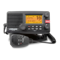
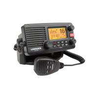
Provides an overview of the Lowrance Link-8 marine band VHF radio's features.
Details how to customize radio settings for individual preferences.
Explains the process of navigating through the radio's menus and options.
Guides users on inputting alphanumeric data using the radio's controls.
Explains the various symbols and their meanings displayed on the radio's LCD.
Describes the different beep tones and call alerts used by the radio.
Instructions for managing the list of stored waypoints.
How to adjust the brightness level of the radio's LCD and keypad.
Guide to managing contacts in the buddy list.
Adjusting receiver sensitivity for local or distant signals.
Adjusting the contrast of the radio's LCD screen for better visibility.
Information on how the radio receives and handles GPS position and time data.
Enabling and using the GPS simulator for testing purposes.
Procedure to restore the radio's settings to factory defaults.
Selecting the appropriate VHF channel bank (USA, International, Canada).
Option to edit or delete custom channel name tags displayed on the LCD.
Adjusting the volume level for incoming DSC call alerts.
Setting the volume for key press feedback or disabling key beeps.
Choosing measurement units for distance and cross track error.
Switching the internal speaker on or off.
Setting the priority channel for US models, similar to Tri Watch.
Configuration options for weather alert notifications.
Configuring the COM port for NMEA communication and data transfer.
Selecting the NMEA source (0183 or 2000) for GPS data input.
Programming a weather channel for quick access via the Wx key (EU/AUS).
Procedure for entering or viewing the mandatory 9-digit User MMSI.
Guide to creating, editing, or deleting groups of contacts.
Entering or checking the ATIS MMSI for inland waterway operations (EU).
Enabling or disabling ATIS functionality, requiring DSC to be off.
Setting automatic or manual responses to incoming individual DSC calls.
Enabling or disabling the DSC function, requiring a valid User MMSI.
Configuring manual, automatic, or no response to LL polling requests.
Enabling or disabling automatic channel switching after a DSC call.
Setting automatic or manual responses to incoming DSC test calls.
Configuring the inactivity timer for automatic timeout of procedures.
Turning the AIS receiver function on or off.
Choosing to display vessel name or MMSI on the AIS plotter.
Setting the NMEA port baud rate for AIS data output.
Redirecting GPS data (RMC, GLL) to the chart plotter via the AIS port.
Enabling or disabling the Closest Point of Approach (CPA) alarm.
Setting the minimum distance for CPA alarms (1NM to 30NM).
Setting the minimum time for TCPA alarms (5Min to 30Min).
Explains Digital Selective Calling (DSC) as an international standard.
Overview of how to initiate DSC calls to other equipped radios.
Procedure for making individual DSC calls to buddies or other stations.
How to acknowledge and respond to an incoming individual DSC call.
Facility to quickly call back the last incoming DSC call.
Procedure for sending DSC calls to pre-programmed groups.
How to send DSC calls to all ships with Safety or Urgency priority.
Accessing and redialing previous incoming calls from the call log.
Viewing and redialing received Distress Calls from the distress log.
Reviewing details of previously sent DSC calls.
Requesting the Latitude/Longitude position of a buddy.
Managing and tracking the positions of selected buddies.
Procedure for sending a DSC test call to verify radio operation.
Displaying the radio's MMSI and current GPS position.
Overview of different types of DSC calls that can be received.
Handling and responding to incoming All Ships DSC calls.
How to handle and respond to incoming individual DSC calls.
Procedure for receiving and responding to group DSC calls.
Handling incoming DSC calls for a specific geographic area.
Receiving GPS position data in response to a buddy's LL request.
Step-by-step guide to initiating a DSC distress call.
How to handle and respond to an incoming distress call.
Handling distress acknowledgements and relay calls.
Responding to incoming individual distress relay calls.
Introduction to the Automatic Identification System (AIS).
Details on static and dynamic information broadcast by AIS devices.
How to view vessel details on the AIS plotter and compatible devices.
Overview of AIS data display on the radio's screen.
Displays target details and geographical position, plus time/CPA data.
Explanation of symbols used on the AIS plotter screen.
How to use the PA system for announcements via the hailer.
Instructions for operating the fog horn feature with various sounds.
Reference chart for VHF marine channels in International regions.
Reference chart for VHF marine channels in the USA.
Reference chart for VHF marine channels in Canada.
List of VHF channels for NOAA and Canadian Weather broadcasts.
Codes and messages for the Emergency Alert System (EAS).
Reference chart for VHF marine channels in EU International regions.
Channel table for Inland Waterways with ATIS ON, country-specific.
List of special channels and their primary usage by country.
| Brand | Lowrance |
|---|---|
| Model | Link-8 |
| Category | Marine Radio |
| Language | English |