Installation and Setup
Transmitter Installation
C
AUTION
::
Do not connect any other devices to the
transmitter. The transmitter requires a
separate power supply.
- Do not mount the antenna near any large
metal objects
NOTE: The transmitter should be charging
whenever not in use.
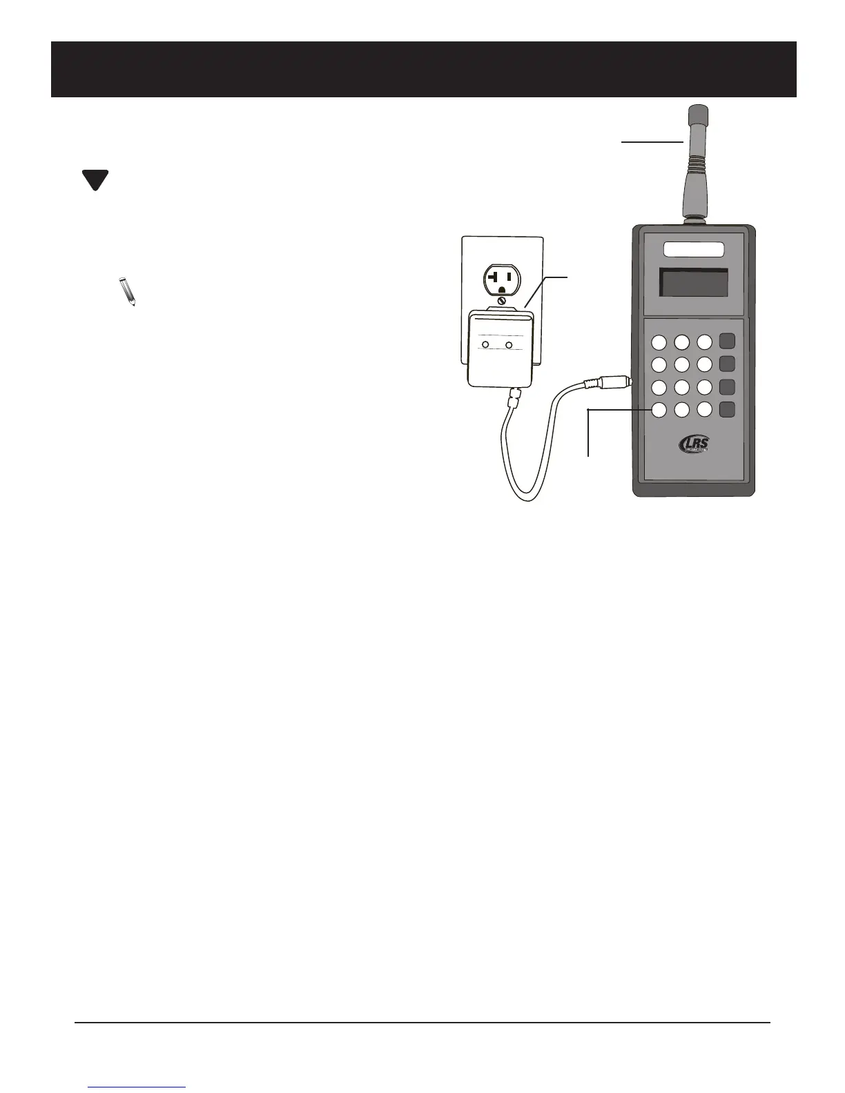
1. Unwrap all transmitter components.
2. Locate the silver connector in the top
of the transmitter. Twist the antenna
(about 3" long) onto connector.
3. The transmitter is transportable and
battery powered and will also run
when connected to the charger.
Mount the power supply in conven-
ient location where there is access to
110V power when charging.
4. Plug the power supply into standard 110V outlet and the barrel connector end
into either of the side holes on the transmitter.
5. Upon completion of setup make sure pagers have good batteries and are powered on.
Keypad Functions
Before you begin using the keypad, read the following keypad descriptions.
MSG Keys Message keys are the last column of keys under the display.
MSG 1 sends message 1 to a staff pager or 30 second flash command to a guest
pager.
MSG 2 sends message 2 to a staff pager or 5 minute flash command to a guest
pager.
MSG 3 sends message 3 to a staff pager or a 5-minute flash, vibe, and beep com-
mand to a guest pager.
MSG 4 sends message 4 to a staff pager or 5-minute glow command to a guest
pager.
Number Keys 1 through 0 are used to enter numeric paging data.
Clr Key This key is used to clear the input when an error is made
Prog Key. This key is used to check and alter the unit programming.
Long Range Systems 3 T9550 LCM User Manual
1
2
3
4
5
6
7
8
9
0
C
L
R
P
R
O
G
L
o
n
g
R
a
n
g
e
S
y
s
t
e
m
s
w
w
w
.
p
a
g
e
r
.
n
e
t
T
9
5
5
0
L
C
M
M
S
G
1
M
S
G
2
M
S
G
3
M
S
G
4
CONDOR
C
L
A
S
S
2
T
R
A
N
S
F
O
R
M
E
R
(
4
0
8
)
7
4
5
-
7
1
4
1
I
N
P
U
T
:
A
C
1
2
O
V
6
0
H
z
1
9
w
O
U
T
P
U
T
:
A
C
9
V
1
8
0
0
m
A
P
/
N
:
A
9
1
A
8
R
o
H
S
U
U
L
L
LISTED
C
M
O
D
E
L
:
4
8
A
-
9
-
1
8
0
0
E
I
A
3
6
3
0
6
3
5
S
M
A
D
E
I
N
C
H
I
N
A
Antenna
Keypad
Transmitter
10 Vac
Power
Supply
 Loading...