Quick Guide function for SpeedControl E 1045
LS Control A/S
Industrivej 12
DK – 4160 Herlufmagle Page 12
Mounting schematics
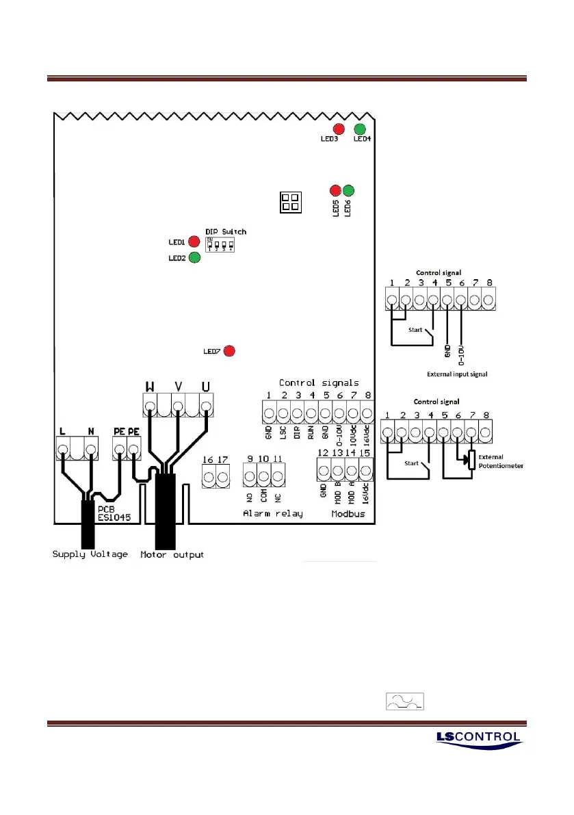
Single phase motors are connected between 2 of the 3 phases out of the frequency converter.
Check the place of installation for any special requirements and precautions which must be observed
during installation, commissioning or operation. The frequency converter must be supplied through a
mains switch with at least 3mm breaker space between all conductors according to IEC364. The fuse
installed in the electrical switchboard must be 13A or less for E1045-1500 and 16A or less for E1045-2000.
The frequency converter must always be connected to yellow/green grounding conductor (PE) in supply.
If the frequency converter is connected to an installation with a residual current device as an extra
protection, the device must be marked with the following symbol: HPFI/PFI
If LSC is not used for Thermal
switch, terminals 1 & 2 must be
shortened
If terminals 16 and 17 (HW Stop
Switch) are not used, these
terminals must be shortened.
JP2 JP1